
User Manual
Page | 3
BDA OVERVIEW:
The BDA assembly enhances the coverage area of radio communications in buildings
and RF shielded environments.
The unit features low noise figure and wide dynamic range. It is a multi-block system,
based on a dual-duplexed (quadruplexer) path configuration with sharp out of band
attenuation allowing improved isolation between the receiving and transmitting paths,
plus Cellular and PCS paths.
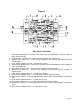
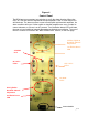
BDA CIRCUIT DESCRIPTION:
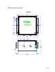
Refer to Figure 1 for the following discussion.
The BDA-CELLAB/PCSF-2/2W-80-OCA1 Downlink path receives RF signals from the
base station, amplifies the signal and transmits the signal, without changing the
frequency, into a Distributed Antenna System at the direction of the mobiles. The
signal travels over a DAS medium that then dissipates the signal to the Mobile
subscribers. The BDA-CELLAB/PCSF-2/2W-80-OCA1Uplink path receives RF signals
at the Mobile side from the DAS system, then amplifies it, and transmits the amplified
signal (without changing the without changing the frequency) to the base station. This
Dual Band BDA supports two Uplink and two Downlink, CELL AB and PSC Full
occupy distinct dedicated frequency bands.
For CELL AB Band, the frequency allocations are as follows:
Uplink: 824-849 MHz
Downlink: 869-894 MHz
For PCS Full Band, the frequency allocations are as follows:
Uplink: 1850-1910 MHz
Downlink: 1930-1990 MHz
The Quad-duplexer isolates the paths and route each signal to the proper amplifying
channel.
An Automatic Level Control (ALC) allows for output power limiting. A variable step
attenuator gives 0 – 30 dB of attenuation in 2 dB steps. The use of these controls is
covered in the “OPERATION” section, later in this document..
OPTIONAL OSCILLATION DETECTS INDICATION:
For an added precaution against oscillations from insignificant antenna separation; a
LED indication is inserted into the BDA’s path. This indication will warn the user to
insert additional manual attenuation to eliminate the oscillation.