
User Manual

Page | 4
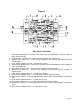
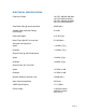
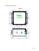
Figure 1
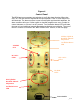
BDA BLOCK DIAGRAM
1. Input Base Quadruplexer – Features low insertion loss and separates UL from DL paths for
CELL and PCS bands.
2. Downlink CELL LNA/Pre-Amp – Low noise figure amplifier with high linearity
3. Selector Filter CELL DL – Features high selectivity and provides required isolation at
maximum gain.
4. Linear Power Amplifier CELL DL – includes ALC circuitry .
5. Output Mobile Quadruplexer – Features low insertion loss and separates UL from DL paths for
CELL and PCS bands.
6. Uplink CELL LNA/Pre-Amp – Low noise figure amplifier with high linearity
7. Selector Filter CELL UL – Features high selectivity and provides required isolation at
maximum gain.
8. Linear Power Amplifier CELL UL – includes ALC circuitry .
9. Downlink PCS LNA/Pre-Amp – Low noise figure amplifier with high linearity
10. Selector Filter PCS DL – Features high selectivity and provides required isolation at maximum
gain.
11. Linear Power Amplifier PCS DL – includes ALC circuitry.
12. Uplink PCS LNA/Pre-Amp – Low noise figure amplifier with high linearity
13. Selector Filter PCS UL – Features high selectivity and provides required isolation at maximum
gain.
14. Linear Power Amplifier PCS UL – includes ALC circuitry.