INSTALLATION AND OPERATING MANUAL BDA-PS7/PS8-2/10W-80-A DUAL BAND BI-DIRECTIONAL AMPLIFIER
TABLE OF CONTENTS PARAGRAPH PAGE NO BDA OVERVIEW BDA BLOCK DIAGRAM DESCRIPTION BDA BLOCK DIAGRAM DRAWING (Figure 1) ELECTRICAL SPECIFICATIONS MECHANICAL SPECIFICATIONS ENVIRONMENTAL CONDITIONS BDA CONNECTIONS MECHANICAL OUTLINE DRAWING (Figure 2 & 2a) BDA INSTALLATION BDA OPERATION UPLINK MECHANICAL OUTLINE- ADJUSTMENT (Figure 3) DOWNLINK MECHANICAL OUTLINE- ADJUSTMENT (Figure 4) RF EXPOSURE WARNING DIAGNOSTICS GUIDE Page 2 3 3 4 5 6 6 6 7 8 9 10 11 12 12
BDA OVERVIEW: The BDA assembly extends the coverage area of radio communications in buildings and RF shielded environments. The BDA has dual RF paths to extend coverage in two distinct frequency bands. The unit features low noise figure and wide dynamic range. It is based on a duplexed path configuration with sharp out of band attenuation allowing improved isolation between the receiving and transmitting paths. BDA BLOCK DIAGRAM DESCRIPTION: Refer to figure 1 for the following discussion.
ELECTRICAL SPECIFICATIONS: Frequency Range Downlink : 764-776 and 851-869 MHz Uplink : 794-824 MHz Pass band Gain @ min attenuation : 80 dB minimum Variable Step Attenuator Range (2-dB steps) : 0-30 dB Pass band Ripple : ±1.5 dB (typ) Noise Figure @+25°C at max gain : 5.
MECHANICAL SPECIFICATIONS: Size : 13.5 x 12.5 x 5.6 inch : (343 x 317.5 x 142.3 mm) RF Connectors : N-type Female Weight : 20.9 Lbs. (9.5kg.) approx. ENVIRONMENTAL CONDITIONS: The unit is designed for indoor applications: Operating temperature: - 20°C to + 50°C Storage temperature: - 50°C to + 90°C BDA CONNECTIONS The BDA AC power is accepted through a standard 3-wire male plug (IEC-320) with phase, neutral and ground leads.
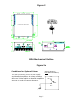
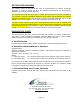
Figure 2 IN BUILDING REPEATER BDA Mechanical Outline Figure 2a (Relay Shown in Non-Alarm Condition) Conditions for Optional Alarm The alarm monitors current of both uplink and downlink amplifiers. An alarm condition will occur if either uplink or downlink amplifiers are over or under its current tolerance. N.O. COM. N.C.
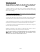
BDA INSTALLATION DO NOT APPLY A.C. POWER TO THE BDA UNTIL CABLES ARE CONNECTED TO BOTH PORTS OF THE BDA AND THE ANTENNAS. 1. Mount the BDA on the wall with the RF connectors pointing DOWN. Using appropriate screws and anchors, attach the BDA to the wall at the four mounting holes on the side flanges. 2. Ensure that the isolation between the donor antenna and the service antenna is at least 12 dB greater than the BDA gain.
RF EXPOSURE WARNING The antenna used for this transmitter must be fixed-mounted on outdoor permanent structures. In order to satisfy the FCC RF exposure requirements, the BDA/antenna installation must comply with the following: The downlink indoor antenna (Omni type or similar directional antenna) must be installed so as to provide a minimum separation distance of 0.35 meters (35 cm) between the antenna and persons within the area. (This assumes a typical antenna with maximum gain of [2 dBi, VSWR >?> 1.