
User's Manual

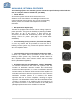


Table Of Contents
- SAFETY OPERATION INSTRUCTIONS
- OVERVIEW
- FCC NOTE
- IC NOTE
- NOTE
- RF EXPOSURE WARNING-FCC
- RF EXPOSURE WARNING- INDUSTRY CANADA
- ELECTRICAL SPECIFICATIONS
- MECHANICAL SPECIFICATIONS
- ENVIRONMENTAL CONDITIONS
- MECHANICAL OUTLINE
- CONNECTIONS
- AVAILABLE, OPTIONAL FEATURES
- ALARM CONDITIONS
- VARIABLE GAIN ADJUSTMENT AND LED INDICATORS
- INSTALLATION
- OPERATION
- DIAGNOSTICS GUIDE
- APPENDIX 1
- APPENDIX 1
- APPENDIX 2

15 | Page
DIAGNOSTICS GUIDE
The BDA provides long term, care-free operation and requires no periodic maintenance.
There are no user-serviceable components inside the BDA.
This section covers possible problems that may be related to the installation or operating
environment.
Gain Reduction
Possible causes: Defective RF cables and RF connections to antennas, damaged antenna or
Leaky cable
.
Occasional Drop-out of some Channels
Possible causes: One channel with very strong power dominates the RF output of the
amplifier
.
Excessive Intermodulation or Spurious
Possible causes: Amplifier oscillation caused by insufficient isolation between two antennas.
See antenna separation paragraph below.
ANTENNA SEPERATION
BDA oscillation is caused by low isolation (antenna separation) between donor antenna and
service antennas. Th
e recommended isolation between those antennas is 15db above the
system gain. The amount of isolation that can be achieved between antennas depends on
several factors, such as the physical vertical and horizontal separation (distance between the
antennas),
polarization, radiation pattern of the antennas, the medium between the
antennas, antenna gain etc.
Antenna isolation can most accurately be determined through on
-site measurements An
antenna isolation measurement configuration is illustrated in Figure
6, where two spatially
separated antennas (service antenna
#1 and donor antenna #2) are connected to a signal
generator and signal analyzer.
A signal at cent
er frequency is generated by the signal generator sent to the input of antenna
1; the output of th
e signal at antenna 2 is measured and recorded by the signal analyzer.
With calibrated connection cables, by taking into account the cable loss, the difference of
signal power level at the output of antenna 2 and that at the antenna 1 input is taken as
ant
enna isolation.
(
See Appendix 2 for analytical calculation)
Figure 6