
User's Manual

MECHANICAL SPECIFICATIONS:
Size : 19.0 x 13.0 x 5.25 inch
: (482.2 x 330.2 x 133 mm)
RF Connectors : N-Type Female
Weight : 23.0 Lbs. (10.45 kg.) approx.
ENVIRONMENTAL CONDITIONS:
The unit is designed for indoor applications:
Operating temperature: - 20°C to + 55°C
Storage temperature: - 50°C to + 90°C
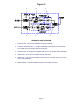
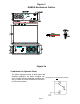
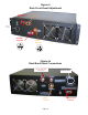
RHBDA CONNECTIONS
The RHBDA Rack AC power is accepted through a standard 3-wire male plug (IEC-
320) with phase, neutral and ground leads (See Figure 3). The AC power is wired to
a high efficiency DC switching power supply which is CE and UL approved. The Rack
power supply runs the amplifiers, the Power ON lamp, and Fiber Optic Transceiver.
The metal enclosure of the RHBDA is connected to ground.
An optional 9-pin D-Sub connector provides failure alarm output contacts (see
diagram next page) as well as an optional 12 VDC (250mA) auxiliary output.
The RF connections are made via three type “N” female connector on the back panel
(See Figure 3). The RF connection on the Rack Unit labeled “MOBILE” must be
connected to the antenna facing the area to be covered by the RHBDA. The RF
connector labeled “UL OUT” must be connected to the RF Source Signal going to the
Base. The RF connection labeled “MOBILE DL” must be connected to the RF Source
Signal from the Base.
The RF connections must be made through cables with characteristic impedance of
50 ohms.
The isolation between the base station antenna and the mobile antenna should
be at least 12 dB higher than the RHBDA gain. Isolation less than this value can
cause gain ripple across the band. Isolation equal to or less than the RHBDA
gain will give rise to oscillations which will saturate the amplifiers and possibly
cause damage to the RHBDA.
Page 6