
Installation Guide
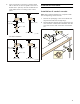

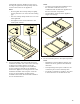
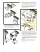

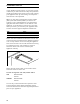
Table Of Contents
- VL 414 110 / AA 490 711
- Table of ContentsInstallation instructions
- IMPORTANT SAFETY INSTRUCTIONS
- WARNING
- WARNING
- WARNING
- WARNING
- WARNING
- Risk of fire
- WARNING
- Risk of fire
- WARNING
- WARNING
- WARNING
- WARNING
- Note:
- Appliance Handling Safety
- Safety Codes and Standards
- Electric Safety
- Related Equipment Safety
- State of California Proposition 65 Warnings
- General notes
- Before You Begin
- Prepare Installation Space
- Note:
- Cutting out countertop
- Hole for control knobs
- 1 As shown in the figure, produce the Ø 1 3/8" (35 mm) holes for fastening the control knobs in the front of the bottom cupboard. A drilling template is provided for exact positioning of the drill holes.
- 2 If the front panel is more than 1" (26 mm) thick: mill out the rear of the front panel so that it is no thicker than 1" (26 mm). Choose the dimensions of the milled recess according to the control panel.
- Installation Procedure
- Installation of control console
- Note:
- 1 Remove the packaging of the control knobs and the protective film from the light rings.
- 2 Hold the bracket against the front panel from the rear. Insert the control knob in the holes from the front and screw it down it from the rear with the nut.
- 3 Using the screws included, bolt down the control panel on the bracket.
- 9 CAUTION
- Note:
- Install Appliance
- Notes
- Notes
- Notes
- 5 Secure the exhaust air pipe to the connecting pieces and seal appropriately..
- Note:
- 6 Plug the control cable of the control unit into the socket on the control desk. Connect the control unit and the fan module with the control cable. All plugs must snap into place. Connect the control unit and fan module to the mains and check that ...
- 7 Flush installation only: it is imperative to test functioning before jointing! Joint the surrounding gap with a suitable, temperature-resistant silicone adhesive (such as OTTOSEAL® S 70). Smoothen the seal joint with smoothing agent recommended by...
- NOTICE:
- Connect Electrical Supply
- Ventilation molding
- Removing appliance
- Installation of control console
- Customer service
- Table de MatièresInstructions d’installation
- CONSIGNES DE SÉCURITÉ IMPORTANTES
- AVERTISSEMENT
- AVERTISSEMENT
- AVERTISSEMENT
- AVERTISSEMENT
- AVERTISSEMENT
- Risque d'incendie
- AVERTISSEMENT
- Risque d’incendie
- AVERTISSEMENT
- AVERTISSEMENT
- AVERTISSEMENT
- AVERTISSEMENT
- Remarque :
- Sécurité de manipulation de l'appareil
- Codes et normes de sécurité
- Sécurité électrique
- Sécurité apparentée concernant l'équipement
- Avertissements de la Proposition 65 de l’État de la Californie
- Instructions générales
- Avant de commencer
- Préparation des meubles
- Remarque :
- Découper le plan de travail
- Trous pour manettes de commande
- 1 Comme indiqué sur la figure, percer des trous Ø 1 3/8” (35 mm) pour fixer les manettes de commande en façade du meuble bas. Pour le positionnement précis des trous, utiliser le gabarit de perçage fourni.
- 2 Si l'épaisseur du bandeau est supérieure à 1" (26 mm) : fraiser l'arrière du bandeau de façon que son épaisseur ne soit pas supérieure à 1" (26 mm). Dimensionner le fraisage selon le pupitre de commande.
- Procédure d'installation
- Pose du pupitre de commande
- Remarque :
- 1 Enlever l'emballage de la manette de commande et retirer le film de protection situé derrière les anneaux lumineux.
- 2 Maintenir la plaque métallique par l'arrière contre le bandeau avant. Emboîter les manettes par devant dans les trous, et serrer par l'arrière au moyen de l'écrou.
- 3 Visser le pupitre de commande à la plaque de maintien au moyen des vis fournies.
- 9 ATTENTION
- Remarque :
- Pose de l'appareil
- Remarques
- Remarques
- Remarques
- 5 Fixer le tuyau d'évacuation à la tubulure et étanchéifier de manière appropriée.
- Remarque :
- 6 Connecter le câble de commande de l'unité de commande dans la prise au pupitre de commande. Connecter le câble de commande à l'unité de commande et au module ventilateur. Toutes les fiches doivent s'encliqueter. Connecter l'unité de commande ...
- 7 Uniquement en cas de montage en affleurement : il faut impérativement effectuer un essai de fonctionnement avant de faire le joint !Garnir le joint périphérique de mastic silicone résistant à la température (exemple : OTTOSEAL® S 70). Lisser...
- AVIS :
- Brancher l'alimentation électrique
- Déflecteur
- Dépose de l'appareil
- Pose du pupitre de commande
- Service après-vente
- ContenidoInstrucciones de instalación
- INSTRUCCIONES DE SEGURIDAD IMPORTANTES
- ADVERTENCIA
- ADVERTENCIA
- ADVERTENCIA
- ADVERTENCIA
- ADVERTENCIA
- Peligro de incendio
- ADVERTENCIA
- Riesgo de incendio
- ADVERTENCIA
- ADVERTENCIA
- ADVERTENCIA
- ADVERTENCIA
- Nota:
- Seguridad con el manejo del electrodoméstico
- Códigos y normas de seguridad
- Seguridad con la electricidad
- Seguridad relacionada con los equipos
- Advertencias en virtud de la Proposición 65 del estado de California
- Información general
- Antes de empezar
- Preparación de los muebles de montaje
- Nota:
- Recortar la encimera
- Perforación para la perilla de mando
- 1 Realice las perforaciones de acuerdo a la figura Ø 1 3/8” (35 mm) para fijar la perilla de mando en la parte frontal del gabinete. Una plantilla de perforación se adjunta para el posicionamiento exacto de los agujeros de taladro.
- 2 Si el panel frontal tiene un espesor superior a 1" (26 mm): Realice un fresado en la parte posterior del panel frontal , de manera que el espesor no sea mayor a 1" (26 mm). Realice las dimensiones del fresado de manera correspondiente al tablero de...
- Procedimiento de instalación
- Montar el panel de mandos
- Nota:
- 1 Retire el embalaje de los módulos de mando y extraiga la lámina de protección de los anillos luminosos.
- 2 Sostenga la lámina de sostén desde atrás contra la pantalla frontal. Introduzca la perilla de mando desde adelante en las perforaciones, y fíjela por detrás con la tuerca.
- 3 Atornille el panel de control a la placa de montaje con los tornillos incluidos.
- 9 ATENCION
- Nota:
- Montaje del aparato
- Notas
- Notas
- Notas
- 5 Fije el tubo de escape en el empalme y séllelo adecuadamente.
- Nota:
- 6 Introducir el cable de control de la unidad de mando en el buje del panel de control. Conectar la unidad de mando y el módulo del ventilador con el cable de control. Todos los enchufes tienen que encajar. Conectar la unidad de mando y el módulo d...
- 7 Sólo para modelos con diseño empotrado a nivel: ¡Antes de cubrir las rendijas, lleve a cabo sin falta una prueba de funcionamiento! La rendija circundante se debe cubrir con un pegamento de silicón adecuado, resistente a altas temperaturas (p. ...
- AVISO:
- Conexión de la alimentación eléctrica
- Guía conductora de aire
- Desmontaje del aparato
- Montar el panel de mandos
- Servicio de atención al cliente

15
Connect Electrical Supply
9 WARNING
Risk of electric shock
Parts inside the appliance can have sharp
edges. The connection cable can be damaged.
Do not bend or pinch connection cables during
installation.
Refer to data plate for more information. See "Service"
for data plate location.
The branch-circuit breakers ampacity, the wire sizes
and the connections must be conform to the
requirements of the National Electrical Code or
Canadian Electrical Code and all local codes and
ordinances.
This appliance is connected with a plug
▯ Plug has to be conform with NEMA
CONFIGURATIONS FOR PLUGS AND
RECEPTACLES.
▯ The appliance must be properly grounded.
▯ Plug must be rated not less than type 6-20 P
(2-pole 3-wire grounding).
▯ Only a qualified electrician should connect the
plug.
▯ Install a socket outlet earthed in accordance with
regulations approx. 27" (700 mm) above the floor
behind the appliance. The socket outlet must still
be accessible after installation.
Ventilation molding
If downdraft ventilation is used next to a gas
appliance, a ventilation molding AA 414 010 must be
fitted on the gas appliance during cooking. The
ventilation molding improves extraction when using
gas appliances. The ventilation molding prevents
extinction of small flames due to the draft.
Removing appliance
Disconnect the appliance from the power supply. For
flush-mounted appliances, remove the silicone joint.
Push out the appliance from below.
9 CAUTION
Damage to appliance! Don't lever device out
from above at the frame.
AA 414 010 Ventilation molding, for operation next
to the VG 414/415/424/425 gas
appliance