
Installation Guide


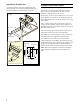


Table Of Contents
- VL 414 110 / AA 490 711
- Table of ContentsInstallation instructions
- IMPORTANT SAFETY INSTRUCTIONS
- WARNING
- WARNING
- WARNING
- WARNING
- WARNING
- Risk of fire
- WARNING
- Risk of fire
- WARNING
- WARNING
- WARNING
- WARNING
- Note:
- Appliance Handling Safety
- Safety Codes and Standards
- Electric Safety
- Related Equipment Safety
- State of California Proposition 65 Warnings
- General notes
- Before You Begin
- Prepare Installation Space
- Note:
- Cutting out countertop
- Hole for control knobs
- 1 As shown in the figure, produce the Ø 1 3/8" (35 mm) holes for fastening the control knobs in the front of the bottom cupboard. A drilling template is provided for exact positioning of the drill holes.
- 2 If the front panel is more than 1" (26 mm) thick: mill out the rear of the front panel so that it is no thicker than 1" (26 mm). Choose the dimensions of the milled recess according to the control panel.
- Installation Procedure
- Installation of control console
- Note:
- 1 Remove the packaging of the control knobs and the protective film from the light rings.
- 2 Hold the bracket against the front panel from the rear. Insert the control knob in the holes from the front and screw it down it from the rear with the nut.
- 3 Using the screws included, bolt down the control panel on the bracket.
- 9 CAUTION
- Note:
- Install Appliance
- Notes
- Notes
- Notes
- 5 Secure the exhaust air pipe to the connecting pieces and seal appropriately..
- Note:
- 6 Plug the control cable of the control unit into the socket on the control desk. Connect the control unit and the fan module with the control cable. All plugs must snap into place. Connect the control unit and fan module to the mains and check that ...
- 7 Flush installation only: it is imperative to test functioning before jointing! Joint the surrounding gap with a suitable, temperature-resistant silicone adhesive (such as OTTOSEAL® S 70). Smoothen the seal joint with smoothing agent recommended by...
- NOTICE:
- Connect Electrical Supply
- Ventilation molding
- Removing appliance
- Installation of control console
- Customer service
- Table de MatièresInstructions d’installation
- CONSIGNES DE SÉCURITÉ IMPORTANTES
- AVERTISSEMENT
- AVERTISSEMENT
- AVERTISSEMENT
- AVERTISSEMENT
- AVERTISSEMENT
- Risque d'incendie
- AVERTISSEMENT
- Risque d’incendie
- AVERTISSEMENT
- AVERTISSEMENT
- AVERTISSEMENT
- AVERTISSEMENT
- Remarque :
- Sécurité de manipulation de l'appareil
- Codes et normes de sécurité
- Sécurité électrique
- Sécurité apparentée concernant l'équipement
- Avertissements de la Proposition 65 de l’État de la Californie
- Instructions générales
- Avant de commencer
- Préparation des meubles
- Remarque :
- Découper le plan de travail
- Trous pour manettes de commande
- 1 Comme indiqué sur la figure, percer des trous Ø 1 3/8” (35 mm) pour fixer les manettes de commande en façade du meuble bas. Pour le positionnement précis des trous, utiliser le gabarit de perçage fourni.
- 2 Si l'épaisseur du bandeau est supérieure à 1" (26 mm) : fraiser l'arrière du bandeau de façon que son épaisseur ne soit pas supérieure à 1" (26 mm). Dimensionner le fraisage selon le pupitre de commande.
- Procédure d'installation
- Pose du pupitre de commande
- Remarque :
- 1 Enlever l'emballage de la manette de commande et retirer le film de protection situé derrière les anneaux lumineux.
- 2 Maintenir la plaque métallique par l'arrière contre le bandeau avant. Emboîter les manettes par devant dans les trous, et serrer par l'arrière au moyen de l'écrou.
- 3 Visser le pupitre de commande à la plaque de maintien au moyen des vis fournies.
- 9 ATTENTION
- Remarque :
- Pose de l'appareil
- Remarques
- Remarques
- Remarques
- 5 Fixer le tuyau d'évacuation à la tubulure et étanchéifier de manière appropriée.
- Remarque :
- 6 Connecter le câble de commande de l'unité de commande dans la prise au pupitre de commande. Connecter le câble de commande à l'unité de commande et au module ventilateur. Toutes les fiches doivent s'encliqueter. Connecter l'unité de commande ...
- 7 Uniquement en cas de montage en affleurement : il faut impérativement effectuer un essai de fonctionnement avant de faire le joint !Garnir le joint périphérique de mastic silicone résistant à la température (exemple : OTTOSEAL® S 70). Lisser...
- AVIS :
- Brancher l'alimentation électrique
- Déflecteur
- Dépose de l'appareil
- Pose du pupitre de commande
- Service après-vente
- ContenidoInstrucciones de instalación
- INSTRUCCIONES DE SEGURIDAD IMPORTANTES
- ADVERTENCIA
- ADVERTENCIA
- ADVERTENCIA
- ADVERTENCIA
- ADVERTENCIA
- Peligro de incendio
- ADVERTENCIA
- Riesgo de incendio
- ADVERTENCIA
- ADVERTENCIA
- ADVERTENCIA
- ADVERTENCIA
- Nota:
- Seguridad con el manejo del electrodoméstico
- Códigos y normas de seguridad
- Seguridad con la electricidad
- Seguridad relacionada con los equipos
- Advertencias en virtud de la Proposición 65 del estado de California
- Información general
- Antes de empezar
- Preparación de los muebles de montaje
- Nota:
- Recortar la encimera
- Perforación para la perilla de mando
- 1 Realice las perforaciones de acuerdo a la figura Ø 1 3/8” (35 mm) para fijar la perilla de mando en la parte frontal del gabinete. Una plantilla de perforación se adjunta para el posicionamiento exacto de los agujeros de taladro.
- 2 Si el panel frontal tiene un espesor superior a 1" (26 mm): Realice un fresado en la parte posterior del panel frontal , de manera que el espesor no sea mayor a 1" (26 mm). Realice las dimensiones del fresado de manera correspondiente al tablero de...
- Procedimiento de instalación
- Montar el panel de mandos
- Nota:
- 1 Retire el embalaje de los módulos de mando y extraiga la lámina de protección de los anillos luminosos.
- 2 Sostenga la lámina de sostén desde atrás contra la pantalla frontal. Introduzca la perilla de mando desde adelante en las perforaciones, y fíjela por detrás con la tuerca.
- 3 Atornille el panel de control a la placa de montaje con los tornillos incluidos.
- 9 ATENCION
- Nota:
- Montaje del aparato
- Notas
- Notas
- Notas
- 5 Fije el tubo de escape en el empalme y séllelo adecuadamente.
- Nota:
- 6 Introducir el cable de control de la unidad de mando en el buje del panel de control. Conectar la unidad de mando y el módulo del ventilador con el cable de control. Todos los enchufes tienen que encajar. Conectar la unidad de mando y el módulo d...
- 7 Sólo para modelos con diseño empotrado a nivel: ¡Antes de cubrir las rendijas, lleve a cabo sin falta una prueba de funcionamiento! La rendija circundante se debe cubrir con un pegamento de silicón adecuado, resistente a altas temperaturas (p. ...
- AVISO:
- Conexión de la alimentación eléctrica
- Guía conductora de aire
- Desmontaje del aparato
- Montar el panel de mandos
- Servicio de atención al cliente

3
9 IMPORTANT SAFETY INSTRUCTIONS
READ AND SAVE THESE INSTRUCTIONS
IMPORTANT SAFETY INSTRUCTION
READ AND SAVE THESE INSTRUCTIONS
INSTALLER: LEAVE THESE INSTRUCTIONS WITH
THE APPLIANCE AFTER INSTALLATION IS
COMPLETE.
IMPORTANT: SAVE THESE INSTRUCTIONS FOR
THE LOCAL ELECTRICAL INSPECTOR'S USE.
WARNING
If the information in this manual is not followed
exactly, fire or shock may result causing property
damage or personal injury.
WARNING
Do not repair, replace or remove any part of the
appliance unless specifically recommended in the
manuals. Improper installation, service or
maintenance can cause injury or property damage.
Refer to this manual for guidance. All other servicing
should be done by a qualified technician.
WARNING
WARNING – TO REDUCE THE RISK OF FIRE,
ELECTRIC SHOCK, OR INJURY TO PERSONS,
OBSERVE THE FOLLOWING
‒ Installation work and electrical wiring must be
done by qualified person(s) in accordance with all
applicable codes and standards, including fire-
rated construction.
‒ Sufficient air is needed for proper combustion
and exhausting of gases through the flue
(chimney) of fuel burning equipment to prevent
back drafting. Follow the heating equipment
manufacturer’s guideline and safety standards
such as those published by the National Fire
Protection Association (NFPA), and the American
Society for Heating, Refrigeration and Air
Conditioning Engineers (ASHRAE), and the local
code authorities.
‒ When cutting or drilling into wall or ceiling, do
not damage electrical wiring and other hidden
utilities.
‒ Ducted fans must always be vented to the
outdoors.
WARNING
The applicable regulations of the energy supply
companies and the regional construction regulations
must be observed when installing the hood.
WARNING
Risk of fire
Grease deposits in the grease filter can catch fire.
Never work with a naked flame near the appliance
(e.g. flambéing). Install the unit near a heat-producing
appliance for solid fuels (e.g. wood or coal) only if
there is a closed, non-detachable cover. There must
be no flying sparks.
WARNING
Risk of fire
Operating several gas burners at the same time gives
rise to a great deal of heat. The ventilation appliance
may become damaged or catch fire. The ventilation
appliance must only be combined with gas burners
that do not exceed the maximum total output of 61,000
Btu/hr (18 kW). If 41,000 Btu/hr (12 kW) is exceeded,
the local regulations concerning room ventilation,
room size, and combination with ventilation devices in
exhaust and recirculating operation must be heeded.
WARNING
To reduce risk of fire and to properly exhaust air, be
sure to duct air outside. Do not vent exhaust air into
spaces within walls, ceilings, attics, crawl spaces or
garages.
WARNING
To reduce the risk of fire, use only metal ductwork.