
Installation Instructions
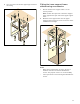
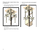
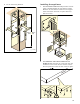
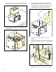
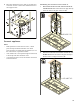


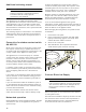


Table Of Contents
- AI 442 720 AI 442 760
- Table of ContentsInstallation instructions
- IMPORTANT SAFETY INSTRUCTIONS
- Installation preparation
- General NotesGeneral Notes
- Before you beginBefore you begin
- Installation
- Appliance Handling Safety
- Transport securing device
- Fitting the upper support frame
- Fitting the lower support frame without using an extension
- Fitting the lower support frame using an extension
- Installing the appliance
- 1 For recirculation mode units only: Fit filters to both sides of the AA 442 810 air recirculation module. Slide the air recirculation module into the support frame from below and hook it in place. Secure it with two screws.
- 2 For combination with internal remote fan unit AR 400 743 only: Unscrew the cover plate from the ventilation hood: Loosen the four screws, remove the cover plate and screw the four screws in again.
- 3 For a combination with external remote fan unit AR4.. only: Use the network cable to connect the external remote fan unit and the ventilation hood’s control module. The plug must snap into place. Connect the mains cable to the control unit.
- Note:
- Note:
- Connect appliance
- Notes
- Establishing the connection for the exhaust air
- 1 Recirculation mode units with internal remote fan unit AR 400 743: Attach the exhaust air pipe directly to the fan motor's air pipe connector (A).
- 2 Extraction mode units with internal remote fan unit AR 400 743: Attach the exhaust air pipe directly to the fan motor's air pipe connector (A).
- 3 Extraction mode units with external remote fan unit AR 4..:
- 4 Connect it to the air extractor opening (B).
- 5 Seal the joints appropriately.
- Connecting the power supply
- Establishing the connection for the exhaust air
- Notes
- Attaching flue duct
- Additional switching output
- Connection for window contact switch AA 400 510
- Networked operation
- Connect Electrical Supply
- Removing the appliance
- Customer Service
- To book a service visit and product advice
- Appliance Handling Safety
- Table des matièresNotice de montage
- CONSIGNES DE SÉCURITÉ IMPORTANTES
- AVERTISSEMENT
- AVERTISSEMENT
- AVERTISSEMENT
- AVERTISSEMENT
- AVERTISSEMENT
- Risque d'incendie
- AVERTISSEMENT
- Risque d’incendie
- AVERTISSEMENT
- AVERTISSEMENT
- AVERTISSEMENT
- AVERTISSEMENT
- Remarque :
- Sécurité de manutention des appareils
- Codes et normes de sécurité
- Sécurité électrique
- Équipement de sécurité
- Avertissement issu de la proposition 65 :
- Préparatifs du montage
- Instructions GénéralesInstructions Générales
- Avant de commencerAvant de commencer
- Installation
- Sécurité de manutention des appareils
- Sécurité transport
- Montage du châssis-support supérieur
- Montage du châssis-support inférieur sans rallonge
- Montage du châssis-support inférieur avec rallonge
- Montage de l'appareil
- 1 En cas de version recyclage uniquement : Mettre en place les filtres des deux côtés dans le module de recyclage de l'air AA 442 810. Introduisez et accrochez le module de recyclage de l’air par en dessous dans le châssis-support. Fixez-le avec...
- 2 Pour la combinaison avec moteur séparé AR 400 743 uniquement : Dévissez la tôle de recouvrement dans la hotte : desserrez 4 vis, retirez la tôle de recouvrement, revissez 4 vis.
- 3 Pour la combinaison avec moteur séparé externe AR4.. : Raccordez le moteur séparé exterrne et le module de commande de la hotte avec le câble secteur. Les fiches doivent s’enclencher. Raccordez le câble secteur au module de commande. Raccor...
- Remarque :
- Remarque :
- Brancher l’appareil
- Remarques
- Effectuer le raccordement de l'évacuation de l'air
- 1 Appareil du mode recyclage avec moteur séparé interne AR 400 743 : Fixez le conduit d’évacuation directement sur le manchon d’évacuation du moteur séparé(A).
- 2 Appareil de mode d’évacuation avec moteur séparé interne AR 400 743: Fixez le conduit d’évacuation directement sur le manchon d’évacuation du moteur séparé (A).
- 3 Appareil de mode d’évacuation avec moteur externe AR 4.. :
- 4 Effectuez la jonction vers l'orifice d'évacuation d'air (B).
- 5 Étanchez les zones de jonction de façon appropriée.
- Effectuer le raccordement électrique
- Effectuer le raccordement de l'évacuation de l'air
- Remarques
- Montage du capot de cheminée
- Sortie de commutation supplémentaire
- Raccord pour le contacteur de fenêtre AA 400 510
- Utilisation en réseau
- 1 Dévisser la tôle de protection.
- 2 Appuyer sur la touche Réinitialiser (Reset) jusqu'à ce que les deux DEL soient allumées en continu (env. 5 secondes). Relâcher ensuite la touche dans les 5 secondes.
- 3 Visser la tôle de protection.
- 4 Faire vérifier le fonctionnement de l'installation par un technicien qualifié après l'initialisation.
- Brancher l'alimentation électrique
- Démontage de l'appareil
- Service après-vente
- Demande de réparation et conseils en cas de dysfonctionnement
- Sécurité de manutention des appareils
- ÍndiceInstrucciones de instalación
- INSTRUCCIONES DE SEGURIDAD IMPORTANTES
- ADVERTENCIA
- ADVERTENCIA
- ADVERTENCIA
- ADVERTENCIA
- ADVERTENCIA
- Peligro de incendio
- ADVERTENCIA
- Riesgo de incendio
- ADVERTENCIA
- ADVERTENCIA
- ADVERTENCIA
- ADVERTENCIA
- Nota:
- Seguridad de manejo del electrodoméstico
- Códigos y normas de seguridad
- Seguridad eléctrica
- Seguridad del equipo relacionado
- Advertencia en virtud de la Proposición 65:
- Preparativos para el montaje
- Información GeneralInformación General
- Antes de empezarAntes de empezar
- Instalación
- Seguridad de manejo del electrodoméstico
- Seguro de transporte
- Montaje del bastidor de soporte superior
- Montar el bastidor de soporte inferior sin prolongación
- Montaje del bastidor de soporte inferior con la prolongación
- Montaje del aparato
- 1 Solo para versión de recirculación de aire: Colocar el filtro en los dos lados del módulo de recirculación de aire AA 442 810. Introducir y enganchar el módulo de recirculación de aire desde abajo en el bastidor de soporte. Sujetar con 2 torn...
- 2 Solo en combinación con un módulo del ventilador interno AR 400 743: Desatornillar la chapa protectora en la campana extractora: desatornillar los 4 tornillos, retirar la chapa protectora, atornillar de nuevo los 4 tornillos.
- 3 Solo en combinación con el módulo del ventilador externo AR4..: Conectar el módulo del ventilador externo y el módulo de control de la campana extractora con el cable de red. Los enchufes tienen que encajar. Conectar el cable de red al módulo ...
- Nota:
- Nota:
- Conectar el aparato a la red eléctrica
- Notas
- Conexión de la salida de aire
- 1 Aparato de modo circulación de aire con módulo del ventilador interno AR 400 743: Sujetar el tuo de salida de aire directamente en la tubuladura de aire del módulo del ventilador (A).
- 2 Aparato de modo de extracción de aire con módulo del ventilador interno AR 400 743: Sujetar el tuo de salida de aire directamente en la tubuladura de aire del módulo del ventilador (A).
- 3 Aparato de modo de extracción de aire con módulo del ventilador externo AR 4..:
- 4 Establecer la conexión con la abertura de salida de aire (B).
- 5 Sellar convenientemente los puntos de unión.
- Montaje de la toma de corriente
- Conexión de la salida de aire
- Notas
- Montar los revestimientos de la chimenea
- Salida de conexión adicional
- Conexión para interruptor de contacto de la ventana AA 400 510
- Funcionamiento conectado
- 1 Desatornillar la tapa protectora.
- 2 Pulsar la tecla Reset hasta que los dos LED se iluminen de forma permanente (aprox. 5 segundos). Después de 5 segundos, soltar la tecla.
- 3 Atornillar la tapa protectora.
- 4 Contactar con profesionales calificados para que comprueben el funcionamiento de la instalación tras el reinicio.
- Conexión de la alimentación eléctrica
- Desmontaje del aparato
- Servicio de atención al cliente

18
Additional switching output
9 WARNING
Work must only be carried out on the additional
switching output by a qualified electrician in
accordance with the country-specific
requirements and standards.
The appliance has an additional switching output
X16(potential-free contact) that can be used to connect
other appliances, such as a ventilation system that is
available at the installation site. The contact is closed
when the blower is switched on, and is opened when the
blower is switched off.
The switching output is located under a cover. Maximum
switching power 30V/1A (AC/DC). The signal that is
connected to the contact must correspond to class of
protection 3.
Connection for window contact switch
AA 400 510
Work on the connection for the window contact switch
must only be carried out by a qualified electrician in
accordance with the requirements and standards of the
country in which in the appliance is being used.
The appliance has a connection (X17) for a window
contact switch. The window contact switch can be flush
mounted or surface mounted. You will receive the
window contact switch AA 400 510separately as an
accessory. Please observe the installation instructions
enclosed with the window contact switch.
If a window contact switch is connected, the extractor
hood's ventilation system will only work with the window
open. The lighting will work even if the window is
closed.
If you switch on the ventilation system with the window
closed, the button for the ventilation setting you have
selected will flash, and the ventilation system will not
switch on.
If you close the window while the ventilation system is
on, the appliance will switch the ventilation system off
within 5 seconds. The button for the ventilation setting
you have selected will flash.
The entire ventilation network and window contact
switch must be assessed by a master chimney sweep.
Networked operation
Several appliances can be networked together. The light
and blower on each of the appliances are operated
synchronously.
Connect the appliances in series via the connector
sockets X1and X2(equal value). The sequence of the
networking does not have any effect. If the enclosed
network cables are too short, use a commercially
available network cable (min. Cat. 5, shielded).
Maximum number of networked appliances: 20. Total
length of all of the network cables: 131 feet (40 m).
During the initial installation, a qualified electrician
must check that the system functions correctly.
If one of the networked appliances fails (power
interruption, network cable disconnected), this leads to
the blower function being blocked for the entire system.
All of the buttons on the appliance flash.
When changing the configuration, the system must be
re-initialized:
1 Unscrew the cover plate.
2 Press and hold the reset button until both LEDs
light up continuously (approx. 5seconds). Then
release the button within 5seconds.
3 Screw on the cover plate.
4 After initialization, have a qualified electrician
check that the system functions correctly.
Connect Electrical Supply
9 WARNING
Risk of electric shock
Parts inside the appliance can have sharp edges.
The connection cable can be damaged. Do not
bend or pinch connection cables during
installation.
Refer to data plate for more information. See "Service"
for data plate location.
The branch-circuit breakers ampacity, the wire sizes and
the connections must conform to the requirements of
the National Electrical Code or Canadian Electrical
Code and all local codes and ordinances.