
Installation Instructions
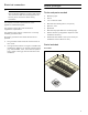
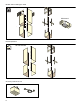
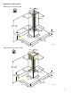
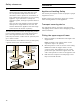
Table Of Contents
- AI 442 720 AI 442 760
- Table of ContentsInstallation instructions
- IMPORTANT SAFETY INSTRUCTIONS
- Installation preparation
- General NotesGeneral Notes
- Before you beginBefore you begin
- Installation
- Appliance Handling Safety
- Transport securing device
- Fitting the upper support frame
- Fitting the lower support frame without using an extension
- Fitting the lower support frame using an extension
- Installing the appliance
- 1 For recirculation mode units only: Fit filters to both sides of the AA 442 810 air recirculation module. Slide the air recirculation module into the support frame from below and hook it in place. Secure it with two screws.
- 2 For combination with internal remote fan unit AR 400 743 only: Unscrew the cover plate from the ventilation hood: Loosen the four screws, remove the cover plate and screw the four screws in again.
- 3 For a combination with external remote fan unit AR4.. only: Use the network cable to connect the external remote fan unit and the ventilation hood’s control module. The plug must snap into place. Connect the mains cable to the control unit.
- Note:
- Note:
- Connect appliance
- Notes
- Establishing the connection for the exhaust air
- 1 Recirculation mode units with internal remote fan unit AR 400 743: Attach the exhaust air pipe directly to the fan motor's air pipe connector (A).
- 2 Extraction mode units with internal remote fan unit AR 400 743: Attach the exhaust air pipe directly to the fan motor's air pipe connector (A).
- 3 Extraction mode units with external remote fan unit AR 4..:
- 4 Connect it to the air extractor opening (B).
- 5 Seal the joints appropriately.
- Connecting the power supply
- Establishing the connection for the exhaust air
- Notes
- Attaching flue duct
- Additional switching output
- Connection for window contact switch AA 400 510
- Networked operation
- Connect Electrical Supply
- Removing the appliance
- Customer Service
- To book a service visit and product advice
- Appliance Handling Safety
- Table des matièresNotice de montage
- CONSIGNES DE SÉCURITÉ IMPORTANTES
- AVERTISSEMENT
- AVERTISSEMENT
- AVERTISSEMENT
- AVERTISSEMENT
- AVERTISSEMENT
- Risque d'incendie
- AVERTISSEMENT
- Risque d’incendie
- AVERTISSEMENT
- AVERTISSEMENT
- AVERTISSEMENT
- AVERTISSEMENT
- Remarque :
- Sécurité de manutention des appareils
- Codes et normes de sécurité
- Sécurité électrique
- Équipement de sécurité
- Avertissement issu de la proposition 65 :
- Préparatifs du montage
- Instructions GénéralesInstructions Générales
- Avant de commencerAvant de commencer
- Installation
- Sécurité de manutention des appareils
- Sécurité transport
- Montage du châssis-support supérieur
- Montage du châssis-support inférieur sans rallonge
- Montage du châssis-support inférieur avec rallonge
- Montage de l'appareil
- 1 En cas de version recyclage uniquement : Mettre en place les filtres des deux côtés dans le module de recyclage de l'air AA 442 810. Introduisez et accrochez le module de recyclage de l’air par en dessous dans le châssis-support. Fixez-le avec...
- 2 Pour la combinaison avec moteur séparé AR 400 743 uniquement : Dévissez la tôle de recouvrement dans la hotte : desserrez 4 vis, retirez la tôle de recouvrement, revissez 4 vis.
- 3 Pour la combinaison avec moteur séparé externe AR4.. : Raccordez le moteur séparé exterrne et le module de commande de la hotte avec le câble secteur. Les fiches doivent s’enclencher. Raccordez le câble secteur au module de commande. Raccor...
- Remarque :
- Remarque :
- Brancher l’appareil
- Remarques
- Effectuer le raccordement de l'évacuation de l'air
- 1 Appareil du mode recyclage avec moteur séparé interne AR 400 743 : Fixez le conduit d’évacuation directement sur le manchon d’évacuation du moteur séparé(A).
- 2 Appareil de mode d’évacuation avec moteur séparé interne AR 400 743: Fixez le conduit d’évacuation directement sur le manchon d’évacuation du moteur séparé (A).
- 3 Appareil de mode d’évacuation avec moteur externe AR 4.. :
- 4 Effectuez la jonction vers l'orifice d'évacuation d'air (B).
- 5 Étanchez les zones de jonction de façon appropriée.
- Effectuer le raccordement électrique
- Effectuer le raccordement de l'évacuation de l'air
- Remarques
- Montage du capot de cheminée
- Sortie de commutation supplémentaire
- Raccord pour le contacteur de fenêtre AA 400 510
- Utilisation en réseau
- 1 Dévisser la tôle de protection.
- 2 Appuyer sur la touche Réinitialiser (Reset) jusqu'à ce que les deux DEL soient allumées en continu (env. 5 secondes). Relâcher ensuite la touche dans les 5 secondes.
- 3 Visser la tôle de protection.
- 4 Faire vérifier le fonctionnement de l'installation par un technicien qualifié après l'initialisation.
- Brancher l'alimentation électrique
- Démontage de l'appareil
- Service après-vente
- Demande de réparation et conseils en cas de dysfonctionnement
- Sécurité de manutention des appareils
- ÍndiceInstrucciones de instalación
- INSTRUCCIONES DE SEGURIDAD IMPORTANTES
- ADVERTENCIA
- ADVERTENCIA
- ADVERTENCIA
- ADVERTENCIA
- ADVERTENCIA
- Peligro de incendio
- ADVERTENCIA
- Riesgo de incendio
- ADVERTENCIA
- ADVERTENCIA
- ADVERTENCIA
- ADVERTENCIA
- Nota:
- Seguridad de manejo del electrodoméstico
- Códigos y normas de seguridad
- Seguridad eléctrica
- Seguridad del equipo relacionado
- Advertencia en virtud de la Proposición 65:
- Preparativos para el montaje
- Información GeneralInformación General
- Antes de empezarAntes de empezar
- Instalación
- Seguridad de manejo del electrodoméstico
- Seguro de transporte
- Montaje del bastidor de soporte superior
- Montar el bastidor de soporte inferior sin prolongación
- Montaje del bastidor de soporte inferior con la prolongación
- Montaje del aparato
- 1 Solo para versión de recirculación de aire: Colocar el filtro en los dos lados del módulo de recirculación de aire AA 442 810. Introducir y enganchar el módulo de recirculación de aire desde abajo en el bastidor de soporte. Sujetar con 2 torn...
- 2 Solo en combinación con un módulo del ventilador interno AR 400 743: Desatornillar la chapa protectora en la campana extractora: desatornillar los 4 tornillos, retirar la chapa protectora, atornillar de nuevo los 4 tornillos.
- 3 Solo en combinación con el módulo del ventilador externo AR4..: Conectar el módulo del ventilador externo y el módulo de control de la campana extractora con el cable de red. Los enchufes tienen que encajar. Conectar el cable de red al módulo ...
- Nota:
- Nota:
- Conectar el aparato a la red eléctrica
- Notas
- Conexión de la salida de aire
- 1 Aparato de modo circulación de aire con módulo del ventilador interno AR 400 743: Sujetar el tuo de salida de aire directamente en la tubuladura de aire del módulo del ventilador (A).
- 2 Aparato de modo de extracción de aire con módulo del ventilador interno AR 400 743: Sujetar el tuo de salida de aire directamente en la tubuladura de aire del módulo del ventilador (A).
- 3 Aparato de modo de extracción de aire con módulo del ventilador externo AR 4..:
- 4 Establecer la conexión con la abertura de salida de aire (B).
- 5 Sellar convenientemente los puntos de unión.
- Montaje de la toma de corriente
- Conexión de la salida de aire
- Notas
- Montar los revestimientos de la chimenea
- Salida de conexión adicional
- Conexión para interruptor de contacto de la ventana AA 400 510
- Funcionamiento conectado
- 1 Desatornillar la tapa protectora.
- 2 Pulsar la tecla Reset hasta que los dos LED se iluminen de forma permanente (aprox. 5 segundos). Después de 5 segundos, soltar la tecla.
- 3 Atornillar la tapa protectora.
- 4 Contactar con profesionales calificados para que comprueben el funcionamiento de la instalación tras el reinicio.
- Conexión de la alimentación eléctrica
- Desmontaje del aparato
- Servicio de atención al cliente

5
9 IMPORTANT SAFETY INSTRUCTIONS
READ AND SAVE THESE INSTRUCTIONS
WARNING
Before you plug in an electrical cord or turn on power
supply, make sure all controls are in the OFF position.
For appliances equipped with a cord and plug, do not
cut or remove the ground prong. It must be plugged into
a matching grounding type receptacle to avoid electrical
shock. If there is any doubt as to whether the wall
receptacle is properly grounded, the customer should
have it checked by a qualified electrician.
If required by the National Electrical Code (or Canadian
Electrical Code), this appliance must be installed on a
separate branch circuit.
WARNING
To reduce the risk of fire or electric shock, do not use
this fan with any solid-state speed control device.
Installer – show the owner the location of the circuit
breaker or fuse. Mark it for easy reference.
Before installing, turn power OFF at the service panel.
Lock service panel to prevent power from being turned
ON accidentally.
WARNING
TO REDUCE THE RISK OF FIRE, ELECTRIC SHOCK,
OR INJURY TO PERSONS, OBSERVE THE
FOLLOWING:
‒ Use this unit only in the manner intended by the
manufacturer. If you have questions, contact the
manufacturer.
‒ Before servicing or cleaning unit, switch power off
at service panel and lock the service disconnecting
means to prevent power from being switched on
accidentally.
When the service disconnecting means cannot be
locked, securely fasten a prominent warning device,
such as a tag, to the service panel.
Be sure your appliance is properly installed and
grounded by a qualified technician. Installation,
electrical connections and grounding must comply with
all applicable codes.
WARNING
Risk of electric shock
Parts inside the appliance can have sharp edges. The
connection cable can be damaged. Do not bend or
pinch connection cables during installation.
Related Equipment Safety
Remove all tape and packaging before using the
appliance. Destroy the packaging after unpacking the
appliance. Never allow children to play with packaging
material.
The appliance should only be used if installed by a
qualified technician in accordance with these
installation instructions. The manufacturer is not
responsible for any damage resulting from incorrect
installation.
Never modify or alter the construction of the appliance.
For example, do not remove leveling legs, panels, wire
covers or anti-tip brackets/screws.
Proposition 65Warning:
This product may contain a chemical known to the State
of California, which can cause cancer or reproductive
harm. Therefore, the packaging of your product may
bear the following label as required by California:
&DQFHUDQG5HSURGXFWLYH+DUPZZZ3:DUQLQJVFDJRY
67$7(2)&$/,)251,$352326,7,21:$51,1*
:$51,1*