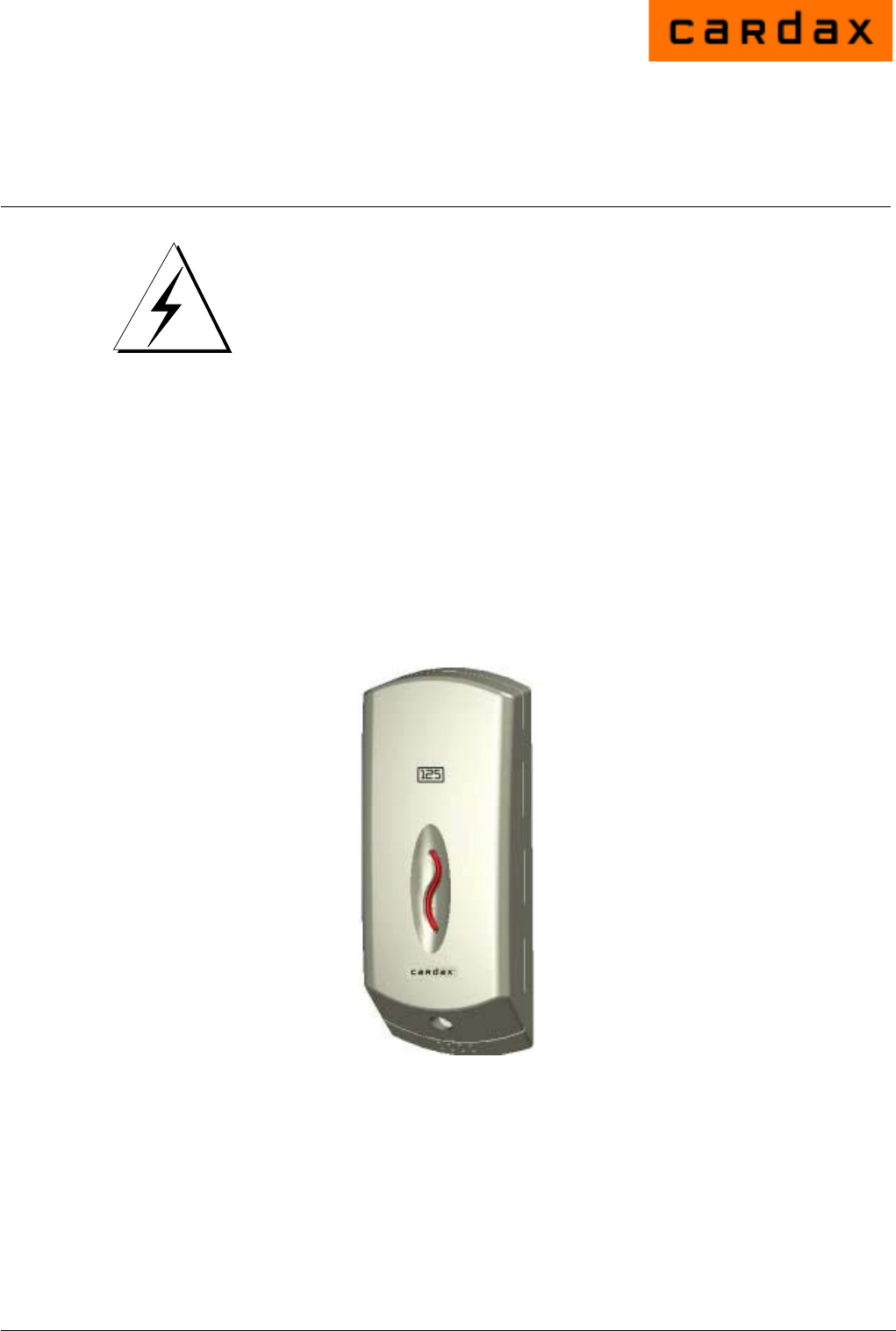
Installation Note Cardax Prox 125 Reader CAUTION This equipment contains components that can be damaged by electrostatic discharge. Ensure both you and the equipment are earthed before beginning any servicing. Before you Begin Unpack the Prox 125 reader and check the shipment contains the following items: • • 1 x Prox 125 base with printed circuit board (PCB) assembly already installed 1 x Prox 125 facia Power Supply Requirements The Prox 125 reader requires a supply of 13.6 V DC ± 15% at 200 mA.
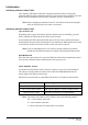
Cabling Use 4 core, 0.2 mm2 (AWG 24) cabling with a maximum, nominal capacitance of 120 pf/m. Maximum distance between the URI and the Prox 125 reader with this type of cable is 200m (650ft). Note: You need a special cable terminating tool to connect the building cabling to the Prox 125. The tool has a head (Part No. C861145) and handle (Part No. C861115). Removing the Facia To remove the facia from the Prox 125 base you need a T10 Torx driver. Use the driver to loosen the screw at the bottom of the facia.
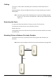
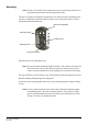
Mounting Note: The Prox 125 reader has been designed to metric specifications therefore any imperial measurements provided are approximate only. The Prox 125 reader is designed to be mounted on any solid flat surface including metal surfaces. In addition the optional cradle base allows you to mount the reader over most standard international flush boxes. Optional Cradle Base Mounting Holes Cabling Hole Mounting Hole Facia Screw Hole Drill the holes for the mounting screws.
Connecting to the URI The Prox 125 reader can connect to either a Cardax IV or CardaxFT URI. Use the cable terminating tool to connect the cables to the socket as described in the following sections. Pin number 4 of the Prox 125 connector feeds into the cable terminating tool first. The pin numbers are marked on the connector. Connecting to the CardaxFT URI Connect the cables to the socket as shown.
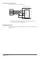
Connecting to the Cardax IV URI Connect the cables as shown in the diagram below. Universal Reader Interface Prox 125 Reader Plug P4 (Exit) or P5 (Entry) 4 3 2 1 Black Blue White Red 1 GND 2 BPR 3 LED 4 DET 5 1-CK 6 0-DT 7 5/12V Note: Refer to Cardax IV URI Settings, later in this Installation Note, for the location of the Cardax IV URI components Replacing the Facia Fit the Prox 125 facia onto the base and tighten the screw at the bottom of the facia using a T10 Torx driver.
Initialisation Initialising with the CardaxFT URI The CardaxFT URI must be allocated a unique unit address which is set up at the CardaxFT URI and at the Command Centre FT Server. Refer to the CardaxFT Universal Reader Interface Installation Note and the Command Centre FT documentation. Note: When configuring Command Centre FT you will need to know the plug (P1 or P2) to which the Prox 125 reader is connected.
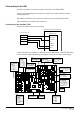
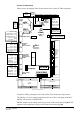
Cardax IV URI Settings Please refer to the diagram below for the location of the Cardax IV URI components. Fuse Fuses (Reader Power (Relay Supply) Contacts) Lithium Battery Lithium Battery Jumper Comms & Power Ground COM B COM A Power P1 J1 F1 F2 D10 F3 P2 D45 5 V DC P8 Comms Out Ground GND Normally Open N.O. Relay Common COM Normally Closed N.C.
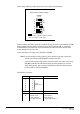
Set the Entry and Exit jumpers for the Prox 125 reader as shown below: Entry and Exit Jumper Settings Cardax 12 V Exit 1 2 3 Entry 4 5 6 = jumper in place Pins 3 and 6 = voltage supplied to reader Pins 1,2 4 and 5 = reader type Connector J2 on the URI controls the Confirmed Entry function. If you initialise the URI with no jumper fitted on J2 the Confirmed Entry function will be ON.
Set DIPSW2 as follows, where 0 = OFF and 1 = ON: Prox 125 only, no authorised exit DIPSW2 12345678 00000000 Prox 125 only, with authorised exit 00000100 Prox 125 with external keypad, no authorised exit 00000011 Prox 125 with external keypad, with authorised exit 00000111 Reader ! CAUTION Do not fit the lithium battery jumper (J1) before powering up the URI. If the jumper is fitted you must remove it and wait 10 seconds. Power up the URI. The yellow LED (D45) should be permanently ON.
Approvals and Standards This equipment has been tested and found to comply with the limits for a Class B digital device, pursuant to Part 15 of the FCC Rules. These limits are designed to provide reasonable protection against harmful interference in a residential installation. This equipment generates, uses and can radiate radio frequency energy and, if not installed and used in accordance with the instructions, may cause harmful interference to radio communications.