
User Manual

Part number 3E0000 R3
April 2002
4
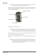
Connecting to the URI
The Prox 125 reader can connect to either a Cardax IV or CardaxFT URI.
Use the cable terminating tool to connect the cables to the socket as described in the
following sections.
Pin number 4 of the Prox 125 connector feeds into the cable terminating tool first.
The pin numbers are marked on the connector.
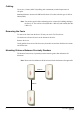
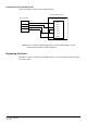
Connecting to the CardaxFT URI
Connect the cables to the socket as shown.
Prox 125 Connector
4
3
2
1
GND
OUTPUTS
OUTPUTS
DET
COMMS
COMMS
5/12V
Plug P1 or P2
CardaxFT Universal Reader Interface
Red
White
Blue
Black
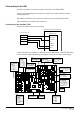
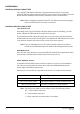
Connect the Prox 125 connector to either the P1 or P2 plug on the CardaxFT URI. Refer
to the CardaxFT URI component layout diagram, below, for the location of the plugs.
1
Q31
D18
U19
T1
R7
R50
R55
R52
R51
R53
R54
JP2
D13
C30
D23
D24
D1
D2
D3
D4
D6
D5
D11
D10
D25
D20
D19
D17
D15
Q7
Q2
P3
D12
D16
D14
Q30
Q29
9
210
1
P8
JP1
0
SW1
E
Q26
1
P7
1
Q27
1
P6
COMM
NC NO
COIL
RLY2
COMM
NC NO
COIL
RLY1
D28
D27
D26
R80
R79
R95
R96
R81
R94
D21
Q28
D22
1
P4
Q41
1
P5
(c)1999 PEC(New Zealand) Ltd
REV[A][B][C]
22825V2 Assy 22826
5V
12V
+
+
GND
GND
IN6 IN5 IN4
OUTPUTSOUTPUTS 5/12V5/12V DETDET COMMSCOMMS GNDGND
COM COMNO NONC NCGND GNDIN3 IN2 IN1 COMMS
P4
Balanced Inputs
pin 1 = Input1
pin 2 = Input 2
pin 3 = Input 3
pin 4 = Input 4
pin 5 = Input 5
pin 6 = Input 6
pin 7 = Ground
P7
Relay Outputs
pin 1 = R1 Normally closed
pin 2 = R1 Normally open
pin 3 = R1 Common
pin 4 = R2 Normally closed
pin 5 = R2 Normally open
pin 6 = R2 Common
pin 7 = Ground
P5
Power & Comms
pins 1 & 2 = RS485
pin 3 = 13.6 V ± 15%
pin 4 = 0V
SW1
Unit address
Set unit number
P8
Diagnostic port
P6
13.6 V ± 15%out
pin 1 = 13.6 V ± 15%
pin 2 = Ground 3A fused
P3
Keypad
pin 1 = Row1
pin 2 = Row 2
pin 3 = Row 3
pin 4 = Row 4
pin 5 = Column1
pin 6 = Column2
pin 7 = Column3
pin 8 = Ground
P2
Non-CardaxFT
Reader 2
pin 1 = 5/12 V power
pin 2 = DataA
pin 3 = DataB
pin 4 = Card detect
pin 5 = LED output
pin 6 = Beeper output
pin 7 = Ground
P1
Non-CardaxFT
Reader 1
pin 1 = 5/12 V power
pin 2 = DataA
pin 3 = DataB
pin 4 = Card detect
pin 5 = LED output
pin 6 = Beeper output
pin 7 = Ground
F1
13.6 V Input Fuse
Rating = 500mA
F2
13.6 V Output Fuse
Rating = 3A
D17
and
D21
Relay state indicators
LED on = Energised
LED off = De-energised
D18
Run LED
D10
Comms LED
flashing = communicating with
FT Controller
JP1
Reader Voltage select
= 5V (200mA total)
= 12V (1A total)
P1
P2