
User Manual

7
Part number 3E0000 R3
April 2002
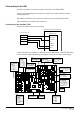
Cardax IV URI Settings
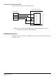
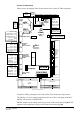
Please refer to the diagram below for the location of the Cardax IV URI components.
Ground
COM B
COM A
Power
P1
P2
P3
P4
P5
Ground
Normally Open
Relay Common
Normally Closed
Door Unlock
Door Open
Push-Button Exit
Ground
Input 1
Input 2
Input 3/*Unlock
Input 4/*Open
Input 5/*Exit
* Applies to 2-Door
URI only
Ground
Beeper
LED
Card Detect
Clock/Data 1
Data/Data 0
5 or 12 V Out
P8
D10
D8
P7
Jumpers
DSW1
D44
DSW2
Comms In
Comms Out
Diagnostics/
Processing
Comms
& Power
Door 1 Inputs
&
Output Relay
Auxiliary
and/or
Door 2 Inputs
Door 1 Exit
Reader OR
Door 2 Entry
Reader
Door 1 Entry
Reader
Door 1
Keypad
1 Top Row
2 Row 2
3 Row 3
4 Bottom Row
5 Left Column
6 Middle Column
7 Right Column
8 Not Used
1 Normally Open
2 Relay Common
3 Normally Closed
Cardax
Prox (125,
Mifare or
TIRIS)/
Cardax
Swipe
12 V
ON
OFF
ON
OFF
Switch On Off
11
22
3 4 Unit
4 8 Address
516
632
7 Initialise Normal
8* *see note below
Switch On Off
1
2 Card Format
3
4
5
6* Validated Exit* Normal*
7* *see note below
8 Keypad No Keypad
* Depends on Software Version.
Tamper
Cardax III
5 V
Wiegand
5 V
Wiegand
12 V
Jumper Connected
No Jumper
D45
5 V DC
Lithium Battery Jumper
Lithium Battery
Fuses
(Relay
Contacts)
J1
J2
OFF
Confirmed Entry
ON
No Confirmed Entry
EPROM
F1
F2
F3
PLD
GND
N.O.
COM
N.C.
UNLK
OPEN
EXIT
GND
AUX1
AUX2
AUX3
AUX4
AUX5
GND
BPR
LED
DET
1-CK
0-DT
5/12V
Ground
Beeper
LED
Card Detect
Clock/Data 1
Data/Data 0
5 or 12 V Out
GND
BPR
LED
DET
1-CK
0-DT
5/12V
Earth Wire
Fuse
(Reader Power
Supply)
Aux. Relay
or Door 2
Relay
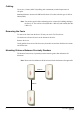
Tamper the URI by opening the door of the cabinet. This releases the tamper switch.
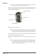
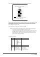
The URI has a set of six jumpers grouped into two sets of three. One group is labelled
ENTRY and the other is labelled EXIT.
ENTRY jumpers set the voltage and card type of the reader connected to plug P5. EXIT
jumpers set the voltage and card type of the reader connected to plug P4.