
User Manual

Part number 3E0000 R3
April 2002
8
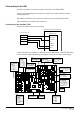
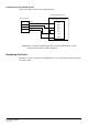
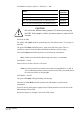
Set the Entry and Exit jumpers for the Prox 125 reader as shown below:
Entry and Exit Jumper Settings
Cardax
12 V
1
2
3
4
5
6
= jumper in place
Pins 3 and 6 = voltage supplied to reader
Pins 1,2 4 and 5 = reader type
Exit
Entry
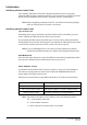
Connector J2 on the URI controls the Confirmed Entry function. If you initialise the URI
with no jumper fitted on J2 the Confirmed Entry function will be ON. To switch the
Confirmed Entry function OFF, you must initialise the URI with a mini-jumper fitted
across both pins of connector J2.
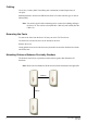
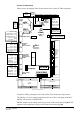
Connect the Prox 125 reader to the URI Entry Plug P5.
Note: If you are using two entry readers (2 door software) you must connect the
second entry reader to URI Plug P4 to initialise the URI.
If you are only using an Exit reader you must connect the reader to the Entry
Plug P5 to initialise the URI. Ensure Entry and Exit jumpers are set to the
same configuration. After you have initialised the URI you should connect
the Exit reader to URI Exit Plug P4.
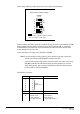
Set DIPSW1 as follows:
Switches On Off
1
2
3
4
5
6
7
8
1
2
4
8
16
32
Unit
Addresses
Initialise
Normal
2 door software
= keypad on door 2
1 door software
= liftcar reader
2 door software
= no keypad on door 2
1 door software
= door reader