
User's Manual


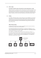
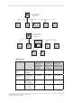
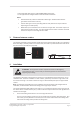
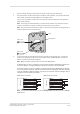


Table Of Contents

Page 7
3E4290 Gallagher T12 Reader | Edion 1 | August 2016
Copyright © Gallagher Group Limited
** Recommended cable types for opmal HBUS RS485 performance.
*** Not applicable for Gallagher mobile credenal reader installaons.
Notes:
• Shielded cable may reduce the obtainable cable length. Shielded cable should be
grounded at the Controller end only.
• If other cable types are used, operang distances and performance may be reduced
depending on the cable quality.
• HBUS allows up to 20 readers to be connected to a single cable. Each reader requires at
least 9 Vdc to funcon correctly. The cable length and the number of readers connected
will have an impact on the voltage at each reader.
3 Distancebetweenreaders
The distance separang any two proximity readers must not be less than 200 mm (8 in) in all direcons.
When mounng a proximity reader on an internal wall, check that any reader xed to the other side of
the wall is not less than 200 mm (8 in) away.
200 mm
200 mm
4 Installaon
ATTENTION: This equipment contains components that can be damaged by
electrostac discharge. Ensure both you and the equipment are earthed before
beginning any servicing.
The Gallagher T12 Reader is designed to be mounted on a standard Brish electrical ush box, or any
solid at surface. However installaon on metal surfaces, parcularly those with a large surface area
will reduce read range. The extent to which the range is reduced will depend upon the type of metal
surface.
Note: Consideraon should be given to the installaon environment when using Gallagher mobile
credenals, as the Bluetooth® wireless technology read range may be reduced.
The recommended mounng height for the reader is 1.1 m (3.6 ) from the oor level to the centre of
the reader device. However this may vary in some countries and you should check local regulaons for
variaons to this height.
1. Ensure the building cable has been run out through the ush box.
If you are not mounng to a ush box, use the reader bezel as a guide to drill all ve holes. Drill
the 13 mm (1/2 inch) diameter centre hole (this is the centre hole for which the building cable
will exit the mounng surface) and the four xing holes.