
User's Manual


Page 5
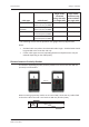
Gallagher T20 Reader
Installaon Note
Document Code: 3E3140
Edion 3, April 2013
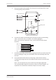
5. Secure the tamper tab (located in the base) to the mounng surface using
remaining xing screw provided.
Base
Building cable
No. 6 pan head screw
Tamper tab
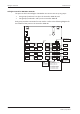
6. Connect the reader tail extending from the facia assembly to the building
cable. Connect the wires, as shown in the following diagram.
Note: Do not cut the “Reserved” wires, as they may be used for future
funcons.
Posive Red
Negave Black
Reserved Orange
Reserved Green
Reserved Brown
CDXIV TX White
CDXIV RX Blue
Cardax IV Reader
7. Fit the facia assembly into the base by clipping the small lip, into the top of the
base and holding the top, press the boom of the facia assembly down into
the base.
8. Insert the M3 Torx Post Security screw (using a T10 Torx Post Security
screwdriver) through the hole at the boom of the base to secure the facia
assembly.
Note: The Torx Post Security screw needs only to be lightly ghtened.
The recommended torque for the security screw is 0.7 Nm (0.5 lb/). It is
important not to exceed the maximum torque of 1.5 Nm (1.1 lb/).