
User's Manual


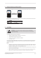
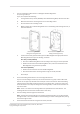
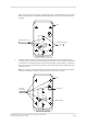
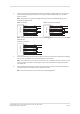
Table Of Contents
- 1 The Gallagher T20 Terminal
- 2 Before you begin
- 3 Distance between proximity readers
- 4 Installation
- 5 Connections
- 6 HBUS LED indications
- 7 Cardax IV LED indications
- 8 T20 Terminal products
- 9 Screen brightness
- 10 Information screen
- 11 Access control icons
- 12 Technical specifications
- 13 Terminal variants feature summary
- 14 Approvals and standards
- 15 Mounting dimensions

Page 4
3E3140 Gallagher T20 Terminal Installaon Note | Edion 16 | March 2016
Copyright © Gallagher Group Limited
1 The Gallagher T20 Terminal
The Gallagher T20 Terminal is available in a variety of variants. The variant you have purchased
determines the available funconality and supported card technologies for the terminal. For variant
details, refer to the "Terminal variants feature summary" on page 16 of this note.
The Alarms Terminal variants (C300463 and C300464) are used for alarms management only, (i.e. do not
contain a smart card proximity reader).
The terminal can be mounted on a rectangular 50 mm x 75 mm (2 in x 3 in) ush box, a BS 4662 Brish
Standard square ush box, a Gallagher Mounng Block (C300930 or C300931) or any solid at surface.
The terminal sends informaon to the Gallagher Controller and acts upon informaon sent from the
Gallagher Controller. The terminal itself does not make any access decisions.
For instrucons on how to use this product, refer to the "3E3685 Gallagher T20 Terminal User Guide"
which can be downloaded from here: hps://security-support.gallagher.com
2 Before you begin
2.1 Shipment contents
Check the shipment contains the following items:
• 1 x Gallagher T20 Terminal facia assembly
• 1 x Gallagher T20 Terminal base
• 2 x 6-32 UNC (32 mm) Phillips drive xing screws
• 2 x M3.5 (40 mm) Phillips drive xing screws
• 5 x 25 mm No.6 self tapping, pan head, Phillips drive xing screws
• 5 x 40 mm No.6 self tapping, pan head, Phillips drive xing screws
• 1 x M3 Torx Post (T10) Security screw
2.2 Power supply
The Gallagher T20 Terminal is designed to operate over a supply voltage range of 9 - 16 Vdc
measured at the readers terminals. The operang current draw is dependent on the supply
voltage at the terminal.
The power source should be linear or a good quality switched-mode power supply. The
performance of the terminal may be aected by a low quality, noisy power supply.