
User's Manual


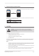
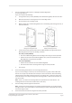
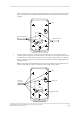
Table Of Contents
- 1 The Gallagher T20 Terminal
- 2 Before you begin
- 3 Distance between proximity readers
- 4 Installation
- 5 Connections
- 6 HBUS LED indications
- 7 Cardax IV LED indications
- 8 T20 Terminal products
- 9 Screen brightness
- 10 Information screen
- 11 Access control icons
- 12 Technical specifications
- 13 Terminal variants feature summary
- 14 Approvals and standards
- 15 Mounting dimensions

Page 5
3E3140 Gallagher T20 Terminal Installaon Note | Edion 16 | March 2016
Copyright © Gallagher Group Limited
2.3 Cabling
The Gallagher T20 Terminal requires a minimum cable size of 4 core 24 AWG (0.2 mm
2
) stranded
security cable. This cable allows the transmission of data (2 wires) and power (2 wires). When
using a single cable to carry both power supply and data, both the power supply voltage drop
and data requirements must be considered. Although the terminal is specied to operate at 9
Vdc, for good engineering design it is recommended that the voltage at the terminal should be
approximately 12 Vdc.
HBUS cabling topology
The HBUS communicaons protocol is based on the RS485 standard and allows the terminal to
communicate over a distance of up to 500 m (1640 ).
The cabling between HBUS devices should be done in a "daisy chain" topology,
(i.e. A "T" or "Star" topology should not be used between devices). Should "Star" or "Home-Run"
wiring be required, the HBUS 4H/8H Modules and the HBUS Door Module allow mulple HBUS
devices to be individually wired to the one physical locaon.
The end devices on the HBUS cable should be terminated using 120 ohms resistance. To
terminate the Gallagher Controller 6000, connect the supplied on-board terminaon jumpers to
the Controller. To terminate the Gallagher T20 Terminal, connect the orange (terminaon) wire
to the green (HBUS A) wire. Terminaon is already included at the HBUS Module, (i.e. each HBUS
port is permanently terminated at the module).
Connect the on-board
terminaon jumper
Controller 6000
RS485 1
HBUS
Device
"T" or "Star" circuits are
not permied between
HBUS devices
HBUS
Device
Terminate
HBUS
Device
HBUS
Device
HBUS
Device
HBUS
Device
HBUS
Device
HBUS
Device
Terminate
Remove the on-board
terminaon jumper
RS485 1
"T" or "Star" circuits are
not permied between
HBUS devices
HBUS
Device
Terminate
HBUS
Device
Controller 6000