
User's Manual


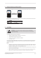
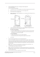
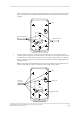
Table Of Contents
- 1 The Gallagher T20 Terminal
- 2 Before you begin
- 3 Distance between proximity readers
- 4 Installation
- 5 Connections
- 6 HBUS LED indications
- 7 Cardax IV LED indications
- 8 T20 Terminal products
- 9 Screen brightness
- 10 Information screen
- 11 Access control icons
- 12 Technical specifications
- 13 Terminal variants feature summary
- 14 Approvals and standards
- 15 Mounting dimensions

Page 8
3E3140 Gallagher T20 Terminal Installaon Note | Edion 16 | March 2016
Copyright © Gallagher Group Limited
1. Are you installing the T20 Terminal on a Gallagher T20 Mounng Block?
If no, then go to Step 2.
If yes, then complete the following:
A. If using the Duct Entry variant (C300931) of the T20 Mounng Block, take the cover o it.
B. Mark the holes for the mounng screws on the mounng surface.
C. Drill the holes for the mounng screws.
D. Make a cabling hole in the Mounng Block and run the building cable through the hole, as
demonstrated next.
Thin Mounng Block with
cabling hole through the back
Duct Entry Mounng Block with
cabling hole through the top
E. Fit the terminal base (pictured at Step 5) to the Mounng Block as appropriate for the
Mounng Block variant you are installing, as follows:
Duct Entry variant (C300931)
• Secure the T20 Mounng Block to the mounng surface using the screws provided.
• Posion the terminal over the Mounng Block cover, and secure them both to the
Mounng Block using the screws provided.
Thin variant (C300930)
• Posion the terminal base over the T20 Mounng Block.
• Secure them both to the mounng surface using the screws provided.
F. Go to Step 6.
2. Ensure the building cable has been run out through the ush box.
If you are not mounng to a ush box, use the terminal base as a guide, to drill all ve holes.
Drill the 13 mm (1/2 inch) diameter centre hole (this is the centre hole for which the building
cable will exit the mounng surface) and the four corner xing holes. Ensure the centre hole
allows the cable to run freely out through the mounng surface, so that the terminal facia can
clip into the base.
Note: There is no room for the building cable to be squeezed into the terminal base. The
building cable must remain within the ush box or wall cavity.
3. Run the building cable through the terminal base.
Note: If the terminal has already been connected to the building cable, you can pass the facia
through the base. Care must be taken to avoid scratching the screen and keypad when passing
the facia through the base.
4. Secure the base to the ush box using the two screws provided.