
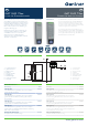
Installation Instructions


DE
EN
DE EN
DE EN
FR
FR
weiß
FR
DE
EN
DE EN
DE EN
FR
FR
weiß
FR
VB_GAT-SLR73xx--DE+EN_23
Gültig ab 5. Februar 2021
Technische Änderungen vorbehalten!
Seite 5
VB_GAT-SLR73xx--DE+EN_23
Valid as of 5
th
February 2021
Technical data subject to modification without notice!
Page 5
GANTNER Electronic GmbH
info@gantner.com
www.gantner.com/locations
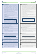
Elektrischer Anschluss - Anschlussbilder
ACHTUNG! Elektrischer Schlag. Trennen Sie immer die Versor-
gungsspannung, bevor Sie elektrische Verbindungen ändern.
Anschluss GAT SLR 7300 / GAT SLR 7310 an GAT DC 7200
1 ...... Mitgeliefertes Standardkabel (Art.Nr.: 869834)
PIN Signal
Adernfarbe
1 IDENT weiß
2 - braun
3 GND grün
4 A (RS 485) gelb
5 B (RS 485) grau
6 GND rosa
7 VOut+
(DC 12-24 V)
blau
8 VOut+
(DC 12-24 V)
rot
2 ...... Geschirmte Datenleitung, paarweise verdrillt (CAT 5 Standard
Farbbelegung laut TIA/EIA -568-B.1-2001 - T568B)
PIN Signal
Adernfarbe
1 IDENT weiß/orange
2 - orange
3 GND weiß/grün
4 A (RS 485) blau
5 B (RS 485) weiß/blau
6 GND grün
7 VOut+
(DC 12-24 V)
weiß/braun
8 VOut+
(DC 12-24 V)
braun
4 ...... RJ45 Buchse für RS-485
Electrical Connections - Diagrams
CAUTION! Electrical shock. Always disconnect the power supply
before altering electrical connections.
Connection of GAT SLR 7300 / GAT SLR 7310 to GAT DC 7200
1 ...... Supplied standard cable (Part No. 869834)
PIN Signal
Wire color
1 IDENT white
2 - brown
3 GND green
4 A (RS-485) yellow
5 B (RS-485) grey
6 GND pink
7 VOut+
(DC 12-24 V)
blue
8 VOut+
(DC 12-24 V)
red
2 ...... Shielded, twisted pair data cable (CAT 5 standard wire
colors as per TIA/EIA -568-B.1-2001 - T568B)
PIN Signal
Wire color
1 IDENT white/orange
2 - orange
3 GND white/green
4 A (RS-485) blue
5 B (RS-485) white/blue
6 GND green
7 VOut+
(DC 12-24 V)
white/brown
8 VOut+
(DC 12-24 V)
brown
4 ...... RJ45 socket for RS-485
GAT SLR 7300 / GAT SLR 7310
GAT SLR 7300 / GAT SLR 7310
GND
VI N+
IDENT
A
B
GND
VI N+
IDENT
A
B
1 2 3 4 5 6 7 8
Reader 1 - 4
2
1
5
4
B
A
GAT Terminal 3100
GND
VOut+
6
5
4
3
2
1
GAT DC 7200
w w w.gant ner.com
Reader 2Reader 1 Reader 3 Reader 4
Relay 1
NC
C
NO
NC
C
NO
NC
C
NO
NC
C
NO
Relay 2 Relay 3 Relay 4 Relay 5
NC
C
NO
NC
C
NO
A
B
A
B
GND
VIN+
Relay 6 Sub
Reader
Power
In 1
IN+
IN
-
IN+
IN
-
IN+
IN
-
IN+
IN
-
IN+
IN
-
IN+
IN
-
In 2 In 3 In 4 In 5 In 6
Ethernet Sub
Reset
Mode
LED 1
LED 2