
Installation Instructions


GAT NET.Lock 7020 System
Installation
32
HB_GAT-NETLOCK7020--EN_12
www.gantner.com
3.11.2 Installation Instructions for the GAT NET.Lock 7020 and Metallic Doors
Complete the following steps to install the GAT NET.Lock 7020 into lockers with metallic doors.
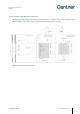
► Drill 3 holes (3) for the GAT NET.Lock 7020 into the locker wall.
NOTE! Position the 3 holes according to the measurements in Figure 3.10.
► Plug the connection cable into the GAT NET.Lock 7020 (see "4. ELECTRICAL CONNECTIONS") and loop the
cable in the bottom of the lock.
► Mount the GAT NET.Lock 7020 with 3 screws (3) on the inside locker wall.
NOTE! Use the correct screws according to the type of locker material, max. Ø 4 mm (0.16 in). The
maximum allowed tightening torque of the screws is 2 Nm (1.47 lb-ft).
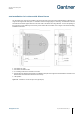
► Cut out a section, 63.4 mm x 68.2 mm (2.5 in x 2.69 in), in the inner wall of the locker door for the GAT
NET.Lock Bolt Set 7220 (8 in Figure 3.11).
► Drill 4 holes (4 in Figure 3.11) in the inner wall of the locker door for mounting the GAT NET.Lock Bolt Set
7220.
► Cut out a section, 67.6 mm x 94 mm (2.66 in x 3.7 in), in the outer wall of the locker door for the label carrier (9
in Figure 3.11).
► Mount the bolt set onto the inside wall of the locker door using 4 screws.
NOTE! Use pan-head metal screws, Ø 3.5 mm (0.14 in), screw length depends on locker door thickness. The
maximum tightening torque of the screws is 2 Nm (1.47 lb-ft).
► Push the label carrier onto the outside wall of the locker door. The label carrier will remain in place with the
lashes on the label carrier. To protect against manipulation, a screw can be used to fix the bolt set to the label
carrier.
NOTE! Use a countersunk screw, Ø 2.9 mm (0.11 in). Screw length depends on the locker door thickness,
e.g., a 15 mm (0.59 in) thick door requires a 19 mm (0.75 in) long screw.
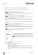
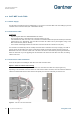
► A label (7) can be attached to the label carrier on the front of the locker door.
The label has a transparent (matt) viewing window for the LED to shine through
and can be ordered with a GANTNER design or customer-specific design.
NOTE! For customer-specific labels, ensure that a transparent field for the status
LED is incorporated in the design and that no metal foil or metal color are used.
Figure 3.12 – Label carrier with front label
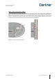
► Test the installation to confirm the following requirements:
o That the locker door closes easily.
o That the door shackle inserts correctly into the GAT NET.Lock 7020. The locker door must spring
open without assistance after it is unlocked.
o When the door is pressed shut, ensure there is no gap between the bolt set (2) and the front of the
GAT NET.Lock 7020. Ideally the bolt set should touch the front of the lock (see measurement in
Figure 3.10).