
Installation Instructions


GAT NET.Lock 7020 System
Installation
www.gantner.com
HB_GAT-NETLOCK7020--EN_12
35
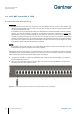
3.13
Installation of the GAT NET.Controller M/S 7020
The GAT NET.Controller M 7020 and GAT NET.Controller S 7020 must be placed in the vicinity of the connected
GAT NET.Lock 7020 locks to keep cable lengths to a minimum. Usually the controllers are placed on top of or
underneath the lockers.
Although the permanent fixing of the controllers is not required (they can simply rest on top of the lockers), when a
controller is to be permanently mounted, e.g., on a wall, use the screw holes provided in the base of the controller.
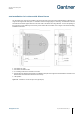
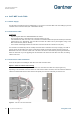
Figure 3.14 - Mounting of the GAT NET.Controller M/S 7020
3.13.1 Instructions for Mounting the GAT NET.Controller M 7020 and S 7020
► Observe the measurements shown in Figure 3.14 and drill 3 holes for the controller mounting points. Use the
correct drill diameter required by the screws and/or wall plugs (screws up to max. M4).
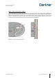
► Screw in the top two screws until the head protrudes approximately 5 mm (0.19 in) out from the wall.
► Attach the controller housing to the top two screws and push down until the housing stops against the screws. If
necessary, remove the controller and tighten the screws as required before rehanging.
► Screw the third screw into the central lower mounting hole and tighten firmly.
► Ensure that the controller is securely fastened and cannot be removed.