
Installation Instructions


GAT NET.Lock 7020 System
Electrical Connections
38
HB_GAT-NETLOCK7020--EN_12
www.gantner.com
4.3
GAT NET.Lock 7020
4.3.1 Power Supply
The GAT NET.Lock 7020 (P) locks are supplied DC 5 V, or DC 24 V for the GAT NET.Lock 7020 USB (P), by the sub
controller via the connection cable (see “7 TECHNICAL DATA”).
4.3.2 Connection Cable
CAUTION!
- Only use original cables from GANTNER Electronic GmbH.
- Do not modify (shorten or extend) the lock connection cable in any way.
- If the standard 5 m cable is too short, use a GAT NET.Lock Cable Extension 3m (Part No. 810021) to extend the
cable length to 8 m. Alternatively, two GAT NET.Lock Cable 5m cables can be joined together using a GAT
NET.Lock Connector (Part No. 442123).
- The maximum cable length between the GAT NET.Lock 7020 and the sub controller is 10 m (26 ft).
The GAT NET.Lock Cable 5m (Part No. 734430) connection cable is included in the scope of supply. The cable is
used to connect the GAT NET.Lock 7020 to a GAT NET.Controller S 7020 sub controller and has a male 4-pin
MOLEX Micro-Fit 3.0
TM
connector on both ends. The cable is the same as used with the previous generation GAT
NET.Lock 7000 locks. If you are upgrading from the GAT NET.Lock 7000 to the GAT NET.Lock 7020, the existing
cables can be used.
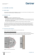
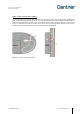
4.3.3 Connection Cable Installation
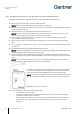
There are two options for installing the GAT NET.Lock 7020 connection cable.
Option 1: Cable exit outside locker housing
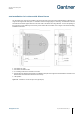
There are five outlets in the housing of the GAT NET.Lock 7020 where the cable can exit (see Figure 4.2).
Depending on the orientation of the GAT NET.Lock 7020 and the cable in the locker, select the outlet that allows the
cable to be installed with minimum effort. Remove the plastic piece from the outlet that you intend to use.
Figure 4.2 - GAT NET.Lock 7020 cable outlets