
Installation Instructions


GAT NET.Lock 7020 System
Electrical Connections
www.gantner.com
HB_GAT-NETLOCK7020--EN_12
39
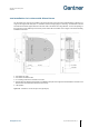
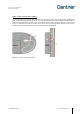
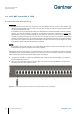
Option 2: Cable exit inside locker housing
This method involves a channel or space in the locker housing being used to route the cable. A hole is drilled in the
locker wall through which the cable is fed and over which the GAT NET.Lock 7020 is installed, thereby providing a
neat “cable-free” appearance. For this method, install the connection cable as shown in Figure 4.3. The circle (1 in
Figure 4.3) represents the cable-exit location in the locker wall. This cable installation method ensures there is
sufficient spare cable at the lock end to aid future lock exchanges or modifications.
Figure 4.3 - GAT NET.Lock 7020 cable routing