
Installation Instructions


GAT NET.Lock 7020 System
Electrical Connections
48
HB_GAT-NETLOCK7020--EN_12
www.gantner.com
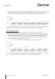
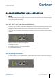
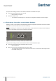
The outputs connect to the corresponding inputs of the controlled device. The supply voltage can be taken from the
GAT NET.Controller M 7020 or supplied by another source. Figure 4.16 is an example of how an external device (3)
can connect to the relay output.
Figure 4.16 also provides an example of how an external device (4) can connect to the optocoupler input.
Figure 4.16 – Relay and optocoupler connection example
NOTE! Adhere to the max. permitted switching voltages and currents, as indicated in "7 TECHNICAL DATA”. Also
read the documentation of the connected device(s) for more information about the electrical connections.