
Installation Instructions


GAT NET.Lock 7020 System
Configuration and Operation
www.gantner.com
HB_GAT-NETLOCK7020--EN_12
51
5.4
Controller LED Signaling and Buttons
5.4.1 Sub Controller
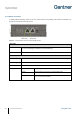
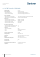
To display different operating states and to start certain functions, the following LED indicators and buttons are
provided on the GAT NET.Controller S 7020.
Figure 5.4 - LEDs and buttons provided on the GAT NET.Controller S 7020
BUTTONS
RESET
1. See "5.2. Restarting a Controller"
2. See "5.3 Resetting a Controller to the Default Settings"
MODE
See "5.1 GAT NET.Lock 7020 Antenna Calibration "
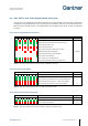
LEDs
RS 485 IN (yellow)
The connection to the master controller has been established
RS 485 IN (green)
RS-485 communication active
LED 1 (blue)
Lock activated/controlled
LED 2 (green/red)
Red:
Emergency operation (no connection to master controller; no
connection to server/software)
Red flashing:
Emergency operation (connection to master controller OK; no
connection to server/software)
Green:
Normal operation (connection to master controller and
server/software OK)
Red/green flashing:
Bootloader mode (a firmware update is currently being loaded or
there is no firmware installed)
Table 5.1 - Buttons and LEDs of the GAT NET.Controller S 7020 sub controller
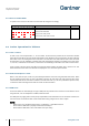
Yellow LED
Green LED