8CH/16CH 2U 5M HYBRID DVR User Manual ganzsecurity.
Copyright This manual without the manufacturer's approved copy and reprinted partially or in full, or translated into another language is prohibited. Limitation of Liability This product is designed to prevent fire and theft is not the main means. We shall not be liable for accidents or damage by using this product can result in liability for accidents or damage In order to improve the performance of the product without prior notice to the product may be a firmware upgrade.
Content OVERVIEW 4 INSTALLATION 10 MONITORING 22 SYSTEM SETTING 34 4 5 6 7 9 Safety Instruction Key Features What's included Rear Panel Remote Control At a Glance 10 15 16 Replacing HDD Basic Layout Connecting to an external device 24 Live Screen At a Glance 34 To move to the System Setup menu Camera Setting Display Setting Audio Setup User Setting Network Setup System Setting Storage Event Setup To start the Record Setup menu Record Setup 35 41 49 50 52 58 65 69 78 79 SEARCH 85 85 85 86
Overview Safety Instruction This product was tested with a UPS to satisfy EN 61000-4-11 test conditions (voltage dips and short interruptions test) under the EN 50130-4: 2011 standard. The Company shall not have any responsibility for any accident or damage that may incur during the use of the product. For your safety, we provide a few instructions about installation, manipulation, cleaning, assembly/disassembly of the product as below. So please read carefully and comply with the instructions.
\\CAUTION Risk of Explosion if Battery is replaced by an Incorrect Type. Dispose of Used Batteries According to the Instructions. Warning to service personnel Double pole/neutral fusing Ethernet Instruction This equipment is indoor use and all the communication wiring are limited to inside of the building or similar word.
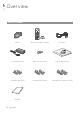
Overview What's included Mouse x1 Remote Control x1 & Batteries (AAA x2) Power Cable x1 DC 12V Adaptor x1 (90W) Adapter cable retainer clip x1 Screws (For fixing HDD / ODD) Terminal Block (7P/for 8CH) x2 Terminal Block (9P for 16CH) x2 Terminal Block 10P (for 16CH x4 / for 8CH x2) Quick Guide 6 | Overview
Rear Panel D- TX RS-232 ALARM OUT AO2 AO1 D+ D- AO4 D+ GND GND RS-485_2 RX AO3 RS-485_1 GND GND IN1 IN3 IN4 IN2 ALARM IN IN8 NC2 PANIC ARI NO1 8 IN7 6 AUDIO OUT 2 GND GND 4 RELAY 7 IN5 5 IN6 3 d NO3 AUDIO IN e NC4 1 c COM3 COM1 COM4 COM2 b Overview \\8 channels SPOT OUT WAN(UPLINK) HD MONITOR RS-232 ALARM OUT AO3 AO4 AO7 AO8 D- TX AO2 AO1 D+ D- D+ RX AO5 AO6 GND GND GND GND IN9 NC6 NO5 RELAY IN1 IN16 IN12 16 GND PANIC 14 IN15 IN11
Overview No. Name Description g HD-MONITOR HD monitor video output port. h e-SATA Connection port for external eSATA storage. i USB Used for connecting USB storage or mouse. WAN(UPLINK) Network port for connection to the Internet, router or hub. j k 8 | Overview LAN(DOWN LINK) DC12V Port for connecting the dedicated network device. Do not share it with other device. Power input port.
Remote Control At a Glance SEARCH Display the search window. ARCHIVE Display the backup window. &, _, p, * Used to change the direction or adjust the play speed in playback mode. EXIT $, %, _, + Use to move through the menus. PANIC Start the emergency recording. SEQ Switch to sequence mode. SETUP Display the system setup menu. MENU Display the tool bar on the live screen. ENTER Select a menu item or apply your settings. NEXT PREV Channel Function as channel selection button in live or playback mode.
Installation Replacing HDD When an HDD is full or problematic, you can replace it with a new one by yourself. \\8 / 16Ch Model Below illustrations are based on the 8/16-channel model. 1. Remove 2 screws on both ends of DVR. 2. Pull the front side of the unit forward to separate it. a b the middle of HDD bracket's handle with index 3. Hold finger and pull it forward while sustaining the bracket handle with your thumb and middle finger as shown in the illustration.
the HDD bracket is separated from the main 4. Once unit, remove 4 screws on both ends of HDD bracket to separate the HDD from the bracket. When installing HDD, make sure to install in the correct direction. the bracket installed with new HDD back into 6. Push the main unit until it is completely inserted. 7. Hold center of the ODD bracket’s holder by your index finger and pull it. English | 11 Installation a new HDD and fasten 4 screws back to both 5. Install ends of the bracket to fix it.
Installation the ODD on the ODD bracket and fix it by 8. Install fastening 4 screws on the bottom of it. M3 9. Insert the bracket with ODD into the main unit, push it until it’s fully inserted. 10. Assemble the front panel back to the unit. JJ When assembling the front panel to the main unit, make sure the marked part is tightly attached. 11. Fasten 2 screws on both ends of the main unit.
\\If installed 5 HDD drives Below illustrations are based on the 8/16-channel model. Installation 1. Remove 2 screws on both ends of DVR. 2. Pull the front side of the unit forward to separate it. a b the middle of HDD bracket's handle with index 3. Hold finger and pull it forward while sustaining the bracket handle with your thumb and middle finger as shown in the illustration.
Installation the HDD bracket is separated from the main 4. Once unit, remove 4 screws on both ends of HDD bracket to separate the HDD from the bracket. a new HDD and fasten 4 screws back to both 5. Install ends of the bracket to fix it. When installing HDD, make sure to install in the correct direction. the bracket installed with new HDD back into 6. Push the main unit until it is completely inserted. 7. Assemble the front panel back to the unit.
Basic Layout AUD 13 15 AUD IO OUT ALARM OUT AO2 AO3 AO4 AO6 GND GND AO7 RS-232 AO8 D+ GND IN15 IN11 D- IN16 IN12 GND PANIC TX AO1 RS-485_1 D+ D- RX RS-485_2 GND GND ARI RELAY IN9 WAN(U 14 PLINK) 16 VGA Speaker SPOT Monitor NO7 NO5 IN HD MONIT OR VGA MONITOR COM7 COM5 COM8 COM6 NC8 NC6 SPO T OUT AO5 15 Camera IN13 IN5 13 VIDEO IN14 IN10 16 11 GND GND RELAY 14 9 IN1 12 7 IN2 11 5 IN3 9 10 NO3 NO1 3 IN4 1 IO IN COM3 COM1 COM4 COM2 NC4 NC2 8
Installation Connecting to an external device \\Connecting to the monitor This product supports 1080p 60 Hz HDMI monitors and regular monitors that support DVI and VGA inputs. Use the switch on the product’s rear side to set it for HDMI or VGA monitor. Connect an HDMI cable to the port on the product’ s rear bottom, or connect an HDMI-DVI converter cable to connect a DVI monitor. Or, use VGA cable to connect the product with a VGA monitor.
AO3 AO4 AO7 AO3 AO4 ALARM OUT GND GND AO7 AO8 AO8 RS-232 GND GND ALARM OUT RS-232 D- D+ TX TX DD+ D+ AO5 AO1 AO1 AO2 AO2 AO6 AO6 RX AO5 D+ D- RS-485_2 DGND GND RS-485_2 RX RS-485_1 GND GND RS-485_1 IN9 IN13 IN15 IN11 IN16 IN12 IN14 IN10 GND GND NC6 GND PANIC ARI ALARM IN GND RELAY IN1 IN2 IN4 ARI IN4 IN7 IN8 IN2 IN1 IN5 IN6 IN3 GND IN3 GND NC4 NC2 NC2 NO5 16 NO7 14 NC8 12 COM7 COM5 COM8 COM6 10 IN7 8 IN8 15 GND 13 IN5 RELAY NO3 NO1 RELAY
Installation AO3 AO4 AO7 AO3 AO4 ALARM OUT GND GND AO7 AO8 AO8 RS-232 GND GND ALARM OUT RS-232 D- D+ TX TX DD+ D+ AO5 AO1 AO1 AO2 AO2 AO6 AO6 RX AO5 D+ D- RS-485_2 DGND GND RS-485_2 RX RS-485_1 GND GND IN9 RS-485_1 NC6 IN16 IN12 IN15 IN11 GND GND GND PANIC NO5 IN1 RELAY NO7 NC8 16 IN13 14 IN14 IN10 12 COM7 COM5 COM8 COM6 10 IN3 8 IN4 IN2 15 ARI NC2 13 IN7 11 IN8 9 GND RELAY NO1 6 IN6 4 7 GND GND 2 AUDIO IN IN5 5 NO3 3 NC4 1 COM3 COM
AO4 RS-232 AO8 13 ALARM OUT D- TX D+ AO3 AO1 AO2 D- D+ AO7 GND GND RX RS-485_2 AO6 AO5 RS-485_1 12 GND GND IN9 NC6 NC8 IN16 IN12 IN13 IN15 IN11 IN14 IN10 GND GND 11 GND PANIC COM7 COM5 COM8 COM6 IN4 IN3 NO5 RELAY 10 NO7 IN1 IN2 ARI NC2 IN8 9 IN7 8 GND 7 NO1 6 RELAY 5 15 IN6 4 IN5 13 NO3 11 NC4 3 9 14 15 AO4 AO3 AO7 AO8 RS-232 GND GND SPOT OUT ALARM OUT D- TX AO1 AO2 D+ D- D+ AO6 RS-485_2 RX AO5 RS-485_1 15 GND GND 13 ALARM
Installation \\Network Connection PC connection in the local network You can connect DVR to a PC in the same network and control or manipulate it on the PC monitor.
PC connection from a remote network AUD IO IN 13 15 AUD IO OUT ALARM OUT AO2 AO4 AO6 AO3 GND GND AO7 RS-232 D+ D- GND IN AO8 IN16 IN12 GND PANIC TX AO1 RS-485_1 D+ D- RX AO5 RS-485_2 GND GND ARI RELAY IN9 NO7 NO5 COM7 COM5 COM8 COM6 NC8 NC6 IN13 SPO T OUT 15 IN14 IN10 13 VIDEO GND GND IN5 11 IN15 IN11 RELAY IN1 16 9 IN2 14 7 IN3 12 5 NO3 NO1 11 10 3 IN4 1 COM3 COM1 COM4 COM2 NC4 NC2 9 8 IN6 7 6 GND GND 5 4 IN7 3 2 IN8 1 WAN(U 14 PLI
Monitoring \\START 1. Connect the adaptor to the power input port on the DVR’s rear side. JJ Make connection when the power is not applied yet. on the power switch in the rear panel of DVR. 2. Turn With a beep, the logo screen appears several seconds after the front LED turns on. the booting process is completed, the live 3. When screen then the login screen appears. \\User Information Setup SET PASSWORD For enhanced security of DVR, enter a new password on DVR boot. 1.
Forgot Password? In case you forgot your password, you can click to verify your E-MAIL and change your password. Monitoring 1. Click . the email address you registered on the initial 2. Enter DVR boot, and then click . to proceed 3. Click with the email verification. 4. Reset the password. \\Log Out To prevent unauthorized access, it is recommended to log out when you leave the screen. 1.
Monitoring Live Screen At a Glance The live screen largely consists of three components: video window, status bar and timeline zone. Video Window Quick Menu Timeline Status Bar \\Video Window Icons used in the video window. Item Camera ID Description Show the camera ID. Displayed if an event recording is reserved. Record Mode Icons Display the status of the continuous recording. Display the recording status when an alarm occurs. Display the recording status when a motion event occurs.
\\Status Bar Press the [▼] button on the remote control, or place the mouse in the lower area of the screen to display the status bar. Description Menu Button Select one of the system setup, search and backup menu items before accessing it. User ID Show the ID of the user who has currently logged in. Edit the screen layout to show the status bar and timeline at all times or only when the mouse cursor hovers on the status bar/timeline. Select a split mode.
Monitoring \\Timeline Press the [▶] button on the remote control or move the cursor to the right of the screen to display the timeline. Double-click the timeline to move to the video screen. Drag and drop it to make backup or event search for the specified area. Item Timeline Date Expand/Collapse the timeline Navigation through Timeline Description 5 Display the date of the current timeline. Click this to select a desired date of the timeline. Expand or collapse the timeline.
\\Using the status bar in the live mode Monitoring Changing Channel You can change channel in LIVE/PLAYBACK screen. Right-click your mouse at the selected channel, and then click the [CAMCHANGE] to select your desired [CAMXX]. Or you can drag & drop your desired channel into the screen to assign.(ex: Changing the channels of CAM1 and CAM2) \\Using the status bar in the live mode Selecting a split mode Click a desired split mode from 1, 4, 9 and 16 split screen.
Monitoring Controlling PTZ You can control PTZ cameras connected to each channel.Use the mouse to click PTZ button on the status bar, or press the [PTZ] button of the remote control to initiate the predefined sequence. In PTZ mode, use buttons on the screen to control PTZ or use [ZOOM], [FOCUS] and [PRESET] buttons of the remote control.
Pan/Tilt Control Monitoring Use mouse to rotate the PTZ camera in the direction of up/down/left/right and diagonal directions. You can control Pan/Tilt with [▲▼◀▶] buttons of the remote control. Zoom / Focus Control You can control the PTZ camera for zooming and focus adjustment. Click button to adjust the camera’s focus automatically. If the connected camera supports manual iris adjustment, you can adjust the iris setting.
Monitoring 2. Control the Camera’s PTZ while watching the video. Press the button to append the preset. : Click the shortcut icon to move to the corresponding PTZ (preset) position. i : Click Delete icon to delete the corresponding preset. i PRESET: Memorizes the PTZ camera’s framing for direct access at a later time. SCAN/TOUR 1. Select and click the button. 2. Click the < > icon. 3. Select a user-defined preset and register it.
Digital Zooming You can enlarge the monitoring screen for better view. 1. Click Zoom in the status bar or move the cursor to a desired channel and right-click it to display the context menu. Select . You can also press the [ZOOM] button on the remote control. to the zoom control screen. When the menu 2. Move bar appears in the right bottom, use the buttons to control the zooming. i i : Select a channel to zoom in/out. : Zoom out the current (enlarged) image step by step.
Monitoring To select an audio input channel Select a channel from which the audio signal will be received. i CHANNEL : Produces the selected channel’s audio, regardless of the split screen mode. i LINK TO FULL SCREEN : When switching the DVR display mode to view one channel (Single Split), it produces the selected channel’s audio. A camera supports audio input should be used, and the DVR is connected to a speaker.
To check the disk status Monitoring You can check status and information on storage devices currently connected to the system. Click to close the window. For more information, refer to "Disk Information". (page 65). Saving captured snapshots You can capture the current video screen and save or export to a connected storage device. 1. Select a channel first, and right click to open popup menu, and select menu item, or press the [SNAPSHOT] button of the remote control.
System Setting To move to the System Setup menu ¯¯ How to use the mouse ENTER ENTER ENTER ENTER SEARCH SETUP SEARCH ¯¯ How to use the remote control 1 MENU MENU MENU ENTER ¯¯ How to use the remote control 2 SETUP 34 | System Setting ENTER ENTER SETUP
Camera Setting System Setting You can configure the display settings of: camera title, hidden option, motion and camera type. \\Camera Type Setup This is used to set up the type of signal for each camera channel. 1. From - , select . the [$%_+/ENTER] buttons on the remote 2. Use controller or the mouse to set the type appropriate for the camera connected. Not all types are compatible therefore check before connecting the camera.
System Setting \\Camera Title You can change the camera ID that is displayed on the screen. 1. From - , select . the [▲▼◀▶/ENTER] buttons on the remote 2. Use control or use the mouse to select a channel that you want to rename. Alternatively, simply double-click the camera to rename from the top left corner. Once the virtual keyboard appeared, select desired 3. alphanumeric characters to complete your input, and press the button.
\\Image Setup You can adjust brightness, contrast, color and quality setting of each channel’s camera. (Not available for HD-SDI cameras.) 1. From - , select . [▲▼◀▶/ENTER] buttons of the remote control or 2. Use mouse to edit settings. i COLOR SETTING : Configures detailed image capturing setup for the camera. i STREAM SETUP : You can specify the camera’s codec, resolution and other properties. 3. To apply your changes, click button.
System Setting \\Motion Sensor Set the motion sensor of the camera so that it can detect a motion event. 1. From - , select . the [▲▼◀▶/ENTER] buttons on the remote 2. Use control or use the mouse to specify the use of each option item. i ACTIVATION : turn on or off the motion sensor. i MARK : Set to to display the motion detection indicator on each video tile where applicable.
the [EXIT] button on the remote control or 5. Press right-click any area to display the popup window as in the right picture. System Setting the popup window is displayed, select 6. While to set the motion detection sensitivity of the channel currently selected. i Channel: Select the channel to set the motion sensitivity. - SENSITIVITY : 1(Low) ~ 30(High) - The higher the number is, the more higher the sensitivity level becomes.
System Setting \\Privacy Mask You can edit privacy mask settings and privacy masking areas for video from each camera. Enabling Privacy Mask For privacy purposes, you can specify masking area for a selected camera's video. 1. From - , select . [▲▼◀▶/ENTER] buttons of the remote or the 2. Use mouse to set channels enabled, mask color and its area. i ACTIVATION : Turns on or off the motion detection sensor in the specified privacy area.
Display Setting \\OSD You can set Camera Name, Icon, Status Bar, Timeline, Borderline, User Name and Language. 1. From - , select . the [▲▼◀▶/ENTER] buttons on the remote 2. Use control or use the mouse to set each option of the OSD item. i CAMERA TITLE : specify the display of the camera title on the screen. i RECORDING MODE ICON : specify the display of the record mode icon on the screen.
System Setting \\Monitor If you change from monitoring mode to sequence, you will have to set the interval of the sequence. 1. From - , select . the [▲▼◀▶/ENTER] button of the remote control 2. Use or mouse to set the dwell for Sequence mode and SPOT Out dwell. i SEQUENCE DWELL : Sets the time interval to the next screen mode for Live monitoring, which defines individual screen mode’s dwell time in the Sequence.
i DISPLAY TYPE : Select which monitor to use as System Setting the main surveillance and the SPOT output. If you selected the SPOT output monitor, click to add the view type. i DISPLAY RESOLUTION : Set the resolution for each monitor. apply the change, click in the bottom of 3. To the screen. done, press the [EXIT] button on the remote 4. When control or click in the lower screen. The confirmation message appears and you will return to the previous menu. \\Sequence Sel
System Setting To add a sequence 1. Click in the bottom of the screen. the "ADD" dialog appears, enter a title using the 2. When virtual keyboard. 3. Enter the name of the sequence and click . the dialog appears, click 4. When . the "SEQUENCE SETUP" dialog appears, select 5. When a split mode that you want to add from . the selected split mode is displayed on , select a channel you want to display in each split screen. 7. Click .
To edit a sequence System Setting 1. Select a sequence that you want to edit in the list. 2. The "EDIT" dialog appears. the [▲▼◀▶/ENTER] buttons on the remote 3. Use control or use the mouse to edit the selected sequence. i SEQUENCE TITLE : enter a new sequence name. i ACTIVATION : specify the use of the sequence. i MODIFY : change the settings of the sequence mode. i DELETE : delete the selected sequence list. i CANCEL : cancel the changes. 4.
System Setting \\SPOT OUT Apart from the main screen display, you can configure the Spot Out to display a Live channel as needed in various live view types. You can set the live view type of display output through the [SPOT] terminal and activate / deactivate it. 1. From - , select . [▲▼◀▶/ENTER] button of the remote control or 2. Use mouse to edit Spot Out properties. i SPOT TITLE : Name the Spot Out setup.
To edit or delete View Type of the SPOT Output System Setting 1. Select an item from the SPOT Output list to be changed. “MODIFY” window appears, click 2. The button. the View Type selection window appears, 3. When select the desired View Type to be edited or deleted, and press [ENTER] button of the remote control or right click on it. i MODIFY : Displays “SPOT SETUP” window for editing View Type and other properties. i DELETE : Deletes the selected View Type. 4.
System Setting \\POS/ATM You can change the settings required to interlock the POS/ATM device connected to DVR. 1. From - , select . the [▲▼◀▶/ENTER] on your remote control or 2. Use use the mouse to change the POS/ATM settings. i DISPLAY MODE : You can select the screen where the data entered from POS/ATM are displayed. - OFF : Nothing is displayed on screen. - BOTH : Both LIVE and PLAYBACK screens are displayed.
Audio Setup \\Audio Choose whether to receive the live sound source and select an audio channel. 1. From -
System Setting User Setting You can configure the settings regarding user management and user and group permissions. \\Management You can add a user account(s) that can be edited at a later time. 1. From - , select . the [▲▼◀▶/ENTER] buttons on the remote 2. Use control or use the mouse to add a user account or select an item that you want to edit. apply the change, click in the bottom of 3. To the screen. done, press the [EXIT] button on the remote 4.
To edit the user account information 1. System Setting From the list of users, select a user account to edit and click next to it. the Edit window, make necessary changes and 2. From click . 3. To delete the user account, click . The account can not be changed or edited. \\Group Authority You can grant different user groups different permissions to a specific menu. 1. From - , select . the [▲▼◀▶/ENTER] buttons or use the mouse 2.
System Setting Network Setup You can set IP address, DDNS and E-mail settings, check network status and RTP. \\IP Setup Specify the IP address as well as the remote service port. 1. From - , select . 2. Use the [▲▼◀▶/ENTER] buttons on the remote control or use the mouse to select one between and . done, press the [EXIT] button on the remote control or click in the lower screen to return to the 3. When previous menu.
IPv6 i IPv6 : You can select OFF or ON for IPv6. System Setting - OFF - ON (MANUAL) - ON (AUTO) i RENEW : The network server restarts and re- allocates IPv6 IP address. i IP ADDRESS : Provide the IP address. i GATEWAY : provide the gateway address. i 1ST DNS SERVER : enter the address of the primary DNS server. i 2ND DNS SERVER : enter the address of the primary DNS server. \\DDNS You can configure the DDNS settings so that remote users who are connected to the network can access remotely.
System Setting \\Email You can register and test an email address so that an email notification is delivered at a specific interval or if an event occurs. 1. From - , select . the [▲▼◀▶/ENTER] buttons on the remote 2. Use control or use the mouse to specify the use of email and select a server. i SERVER : Set up the mail server. Set the mail server that will be used for notification to the DVR. Use the virtual keyboard to enter your mail server.
\\Network Status 1. From - , select . the [▲▼◀▶/ENTER] buttons on the remote control or use the mouse to select one between 2. Use and . done, press the [EXIT] button on the remote control or click in the lower screen. The confirmation 3. When message appears and you will return to the previous menu. Network Map i IP ADDRESS : Indicates the internal IP address of the DVR.
System Setting \\Security For security purpose, you can set whether to use encryption and its method, and configure IP filtering. - , select 1. From . the [▲▼◀▶/ENTER] buttons on the remote 2. Use control or use the mouse to select one between and . done, press the [EXIT] button on the remote 3. When control or click in the lower screen to return to the previous menu.
\\RTP done, press the [EXIT] button on the remote control or click in the lower screen. The confirmation 3. When message appears and you will return to the previous menu. RTP i PORT RANGE : Set the range of port number for RTP UDP transfer, which will be dynamically allocated. i MODE : Set the port allocation method for “RTP Audio back channel”. Set to for automatic allocation, or to to use specified port in the PORT attribute.
System Setting System Setting You can configure the settings of date/time, system management, system information, control device, POS/ATM and Secuity. \\Date/Time Specify the current date and time. 1. From - , select . the [▲▼◀▶/ENTER] buttons on the remote 2. Use control or use the mouse to change the time or set the options as necessary. i DATE/TIME : Set the current time and date. Click< > to adjust the time manually. i DATE FORMAT : specify the date format.
\\System Management You can check, update or reset the system information. From - , select . System Setting 1. the [▲▼◀▶/ENTER] buttons on the remote control 2. Use or use the mouse to set each option of the system management. i FW UPDATE : you can update the current software with the latest version. i FACTORY DEFAULT : Return the DVR settings to the factory default.
System Setting - LOAD : Apply the settings of the storage device to the DVR. Connect the storage device to the USB port of DVR. i NETWORK SETUP WIZARD : Triggered when the corresponding button is pressed or upon factory initialization. The wizard guides through network configuration such as setting the DHCP or static IP address, WEB and RTSP service ports. i SYSTEM ID : Assign an ID to the DVR to distinguish it out from others when there are multiple DVR used. The default value is “SYSTEM ID”.
To perform the upgrade 1. System Setting Connect the USB storage device that contains the updatable files. 2. Click . one(s) from the updatable files listed in . 4. Click . 5. When the confirmation message appears, click . progress bar displays the progress of the 6. The firmware upgrade process. 7. When the upgrade is complete, reboot the system.
System Setting \\System Information You can check the current system version and system-related settings. 1. From - , select . 2. Check the status of the current system. done, press the [EXIT] button on the remote 3. When control or click in the lower screen. The confirmation message appears and you will return to the previous menu. \\Control Device Configure the settings of the remote control and keyboard controller. 1.
\\POS/ATM You can check the configuration of the POS/ATM device connected to DVR. From - , select . System Setting 1. the [▲▼◀▶/ENTER] on your remote control or 2. Use use the mouse to check the POS/ATM settings. i ACTION : Specify whether to activate the POS/ ATM device or not. i TYPE : Display the type for each channel. i PORT : Display the port for each channel. the data for each required item, and then 3. Change press the button. 4.
System Setting \\Security For security, you can set to apply reinforced password policy (to system, search/backup) and control accessing snapshot. 1. From - , select . the [▲▼◀▶/ENTER] buttons on the remote 2. Use control or use the mouse to set each option of security. i AUDIO SUPPORT : Allows audio function. If set to , all audio functions are disabled. Live and playback screen do not produce audio, and no audio recording is allowed.
Storage System Setting You can configure the settings of and view information of the disk and external storage device. \\Disk Information It will show information about the connected disk. 1. From - , select . the [▲▼◀▶/ENTER] buttons on the remote 2. Use control or use the mouse to select either or . Please check the status for each connected device.
System Setting \\Disk Operations You can set to delete the recording automatically and set the overwrite options, and you can also format the HDD recording data. 1. From - , select . the [▲▼◀▶/ENTER] buttons on the remote 2. Use control or use the mouse to set the operation conditions of the disk.
1. From - , select . System Setting the [▲▼◀▶/ENTER] on your remote 2. Use control or use the mouse to change your DISK CONFIGURATION. i MODEL : Display the model of each disk. i CAPACITY : Display the capacity of each disk. i STATUS : If any problem occurs in the disk where a RAID array has been configured, the disk is displayed as Degrade. i REBUILD : Display whether to rebuild each disk or not. i REFRESH : Reload the status of the RAID array.
System Setting \\S.M.A.R.T settings You can check the S.M.A.R.T information of the disk and specify the check frequency. What is S.M.A.R.T information? S.M.A.R.T (Self-Monitoring, Analysis and Report Technology) is to detect a HDD that is likely to cause a problem in the future with a warning message. - , select 1. From . the [▲▼◀▶/ENTER] buttons on the remote 2. Use control or use the mouse to check the S.M.A.R.T operation and specify the check interval.
Event Setup System Setting Define various events, and specify the conditions to notify the user in various ways. \\Alarm Out Specify the alarm output conditions with the work schedule. Alarm Out 1. From - , select . the [▲▼◀▶/ENTER] buttons on the remote 2. Use control or use the mouse to select and configure the related settings. i NAME : You can rename the alarm. i OPERATION : Set the alarm output mode. - N/O (Normal Open) : It normally stays Open.
System Setting ON/OFF Schedule You can activate or turn off the alarm output as scheduled. 1. Use the [▲▼◀▶/ENTER] buttons on the remote control or use the mouse to select a for the schedule. the mouse to resize the cell or use the on the 2. Drag [▲▼◀▶] buttons to move to the cell, then press [ENTER]. 3. Select a desired alarm output mode. i ON : The alarm output is always turned on. i OFF : The alarm output is always turned off. i EVENT : Trigger the alarm output in sync with the event.
\\Event Notification 1. From - , select . the [▲▼◀▶] buttons on the remote control or use the mouse to select one from , and 2. Use . 3. Use the [▲▼◀▶/ENTER] buttons on the remote control or use the mouse to set the output method and duration. 4. To apply the change, click in the bottom of the screen. done, press the [EXIT] button on the remote control or click in the lower screen. The confirmation 5.
System Setting Email If an event occurs, this will notify registered users of the event by email. If you do not want to receive the email, uncheck the option in . (Page 50) i ADD NEW EMAIL If you want to add a new mail recipient beside the existing ones, click this to add the recipient. i MINIMUM EMAIL FREQUENCY Adjust the minimum frequency of sending the email.
\\Alarm Sensor You can configure the settings of the alarm sensor and specify the operation of the sensor if an event occurs. From - , select . System Setting 1. the [▲▼◀▶] buttons on the remote control or use the 2. Use mouse to specify the sensor input method and operation. i NAME : You can specify the name of the alarm sensor. i OPERATION : You can specify the type of the alarm sensor. - N/O (Normal Open) : Normally the sensor is left Open.
System Setting \\Motion Sensor You can set an action to execute when a motion is detected. For the settings of the motion sensor, move to . 1. From - , select . the [▲▼◀▶] buttons on the remote control or 2. Use use the mouse to specify the ignorance interval and operation. i IGNORING INTERVAL : Specify the minimum interval of the motion event occurrence.
\\Video Loss You can specify a reaction to the case where no video is received from the camera. From - , select . System Setting 1. the [▲▼◀▶] buttons on the remote control or use 2. Use the mouse to specify the reaction to a video loss i ALARM OUT : Specify the alarm output channel if a video loss occurs. i i i : Specify the output of the buzzer if a video loss occurs. : Select to send an email if a video loss occurs.
System Setting \\System Event You can set any action to an event related to the disk, recording, network or system. Like the other events, you may notify the event to the user using the alarm/buzzer output, OSD pop-up or email. 1. From - , select . 2. Use the [▲▼◀▶] buttons on the remote control or use the mouse to specify the reaction to each event. 3. To apply the change, click in the bottom of the screen.
System i BOOTING EVENT: This event occurs when the System Setting DVR is booting. i LOGIN FAIL EVENT: This event occurs when the DVR fails to log in. You can specify the times of clicking < trigger the event. > to i FAN FAIL EVENT : This event occurs if the CPU cooling fan or unit's cooling fan does not work at all. If the fan fails, no recording will proceed by the DVR. If you encounter a fan failure, contact the retailer or the service center for technical assistance.
Record Setting You can configure the record settings for the DVR. Only authorized users can access the Record Setup menu.
Record Setup You can set the recording options for Auto or Manual mode. 1. From menu, select . the [▲▼◀▶] buttons or use the mouse to set to or . 3. Set the recording options for each selected Record mode. 4. To apply the change, click in the bottom of the screen. done, press the [EXIT] button on the remote control or click in the lower screen. The confirmation 5.
Record Setting Manual Configuration If you set the record mode to , the manual configuration window will appear where you can set the manual recording and panic recording options. i MANUAL CONFIGURATION OPTIONS : You can configure the recording settings by the time, date, and channel. - SCHEDULE MODE : Set the recording schedule for a day (daily) or for a week (weekly). - PRE RECORDING TIME : Set the pre-recording time. - POST RECORDING TIME : Set the postrecording time.
\\Continuous Recording 1. From the menu, select . From , you must set to before you can set the . the [▲▼◀▶] buttons on the remote control or use the mouse to select either or 2. Use . Size/FPS/Quality Setting 1. Please select the day of the week to perform the continuous recording.
Record Setting Schedule Setting 1. Select a start day of the week on the schedule. a time cell from which you want to make the 2. Click schedule and drag it to a desired cell. Or use the [▲▼◀▶] buttons on the remote control to move to the cell and press [ENTER]. Then, use the [▲▼◀▶] buttons to move to a desired cell and press [ENTER] again. the time selection is complete, you will be 3. When prompted to specify the use of recording in the Record Setup window.
\\Alarm Recording Specify the recording size of the alarm event if it occurs and make schedule for that recording. From the menu, select Record Setting 1. the [▲▼◀▶] buttons on the remote control or use 2. Use the mouse to select either or . Set each item of , , 3. and use of the
Record Setting \\Network Streaming You can specify the maximum size of network streaming for remote users and set the FPS. 1. Even if you set the resolution and FPS to high for the network streaming, the DVR will reduce the size or FPS according to the network status (speed) before transferring the recording video. From the menu, select . the [▲▼◀▶/ENTER] buttons on the remote 2. Use control or use the mouse to select an item that you want to edit. 3.
Search You can search for the recording data in the HDD by the criteria of time, thumbnail, event, text-in, etc.
Search Search Settings \\Time Search With the calendar, you can search for the recording data by the recorded date. 1. From the menu, select
\\Thumbnail Search 1. Search To improve your search, you will be provided with a list of thumbnails. Select Day, Hour or Minute to narrow down the search results. From the menu, select . the [▲▼◀▶] buttons or use the mouse to specify 2. Use the search date and time from the calendar in the left corner of the thumbnail search screen. i FIRST : The first date of recording is automatically selected. i LAST : The last date of recording is automatically selected.
Search \\Event Search Search for events that occurred at the specified time and select an event to play from the list. 1. From the menu, select . the [▲▼◀▶] buttons or use the mouse to specify 2. Use the and times in the left of the event search list. 3. Select a channel to search. the checkbox of the event to search from the 4. Mark list. the button. 5. Press The search results will be listed as shown. i TYPE : displays the event type.
\\Text-in Search You can search for the text generated at a predefined time and select the text from the list to playback. Search 1. From the menu, select . the [▲▼◀▶] on your remote control or use the 2. Use mouse to specify the and times on the left of the EVENT SEARCH list. 3. Select the check box(es) for the channel(s) to search. the keyword in - to search 4. Enter for. i MATCH CASE : Perform a case-sensitive search for the keyword entered.
Play If you want to play 1. To play the searched data - You can search for and play a searched data. 2. To play with the live viewer - Simply double-click a desired time point in the right corner of the play screen. If you move the cursor to the rightmost, the "Timeline" bar will be displayed. - Select a desired channel in the live screen and right-click to select in the context menu. Then, select a desire play time. \\Playback screen configuration Video Window Playback channel selection
Playback channel selection menu CAM1 ZOOM START BOOKMARK SNAPSHOT CAM CHANGE Description Display the title of the selected channel. Zoom the video of the selected channel. (The zooming function is active only in '1' split screen.) The "Set bookmark" popup appears, and you can bookmark a play point for the backup purpose. Capture the current live video and save it in the .jpeg format. You can assign the selected screen to another channel.
Play Bookmarking During playback, you can add a bookmark for reserving the video data. You can view the bookmarked data in the Archive menu, which can be saved to a connected device for the backup purpose. 1. Provide a tag in the item for data reservation. the details of the reserved data in the 2. Provide input box. . 3. Click You will return to the play screen with the backup progress. 4. To stop the bookmarking, click . quit the bookmarking, click . 5.
Archiving To start the Archive menu Archiving Using the Archive menu during playback 1. During the playback, click . 2. The "ARCHIVING SETUP" window appears where you can reserve the data. 3. Click in the lower left corner and select the menu. 4. Press the [ARCHIVE] button on the remote control. Using the Archive menu during monitoring 1. Click in the lower left corner and select the menu. 2. Press the [ARCHIVE] button on the remote control. \\Arc
Archiving \\Reserved data management You can search for the reserved data and delete or import it to a storage device. 1. From the menu, select . The reserved data will be listed. a data type from and . i AVI : Searches AVI video files stored in the DVR. i SNAPSHOT CAPTURE : Searches captured snapshots stored in the DVR. you want to play the data, double-click a desired 3. Ifdata item or click it and select .
\\Archive Devices Setup Provide the FTP server information for archiving data in the HDD before testing the transfer. From the menu, select . Archiving 1. 2. Move to the FTP information box. 3. Fill in each item using a virtual keyboard. i HOST NAME : enter the address at which you can access the server. i PORT : enter the port number to which you can access the server. i USER NAME : enter the user ID with which you can access the server.
Web Viewer What is the Web Viewer? Web RA is a user-friendly software application that enables you to control the video data in connection with a remote DVR. \\System Requirements The following is the minimum hardware and operating system requirements to run Web RA. Operating System Web browsers: CPU Memory Display Hard Disk Drive Windows XP Professional Windows Vista Home Baisc / Premium Window 7 Internet Explorer 7.0 or later/Mozilla Firefox 3.6/Google Chrome 4.
1. Provide the user ID and password. Web Viewer The initial administrator ID is “ADMIN” and the password should be set when logging in for the first time. 2. Click the lower warning bar to install the ActiveX. If you fail to download the ActiveX control, move to Tools Internet Options Security Custom Level Download unsigned ActiveX control, and change its setting from “Disable (recommended)” to “Enable”, and then click OK. 3. Click . the installation is complete, you will see the live 4.
Web Viewer Live \\Live Screen At a Glance a b c h d g f e No. Item Description a View selection tab You can switch to the live, playback and setup screen and check the provided information. b Live Display the live screen of the currently connected DVR. c Split Mode Select and switch to a desired split-screen mode. d Sequence, Zoom Set the sequence mode, switch to the next camera, zoom the screen or select the full screen mode. Status Show the connection status of each channel.
Item Description f Voice transmission You can turn on or off the output of the voice signal. g Channel Select a channel listed in the screen. Save Save the live video on the screen. Print Print out the current screen. Capture Capture the selected image. ActiveX Settings Configure the ActiveX settings or specify the saving path of the captured image. h Web Viewer No. \\Switching the split mode Click the Switch button to switch the mode as follows: <1-split Mode> <4-split Mode> <8-split
Web Viewer \\To save the video 1. Click < > to start saving. 2. The video from the selected channel will be saved to the PC in the AVI format. (Default path: C:\SaveFolder) Click < > again to stop saving. Click to display the context menu where you can change the saving path. \\Print 1. Click < >. 2. The current screen will be printed with the printer connected to the PC. \\Screen capture 1. Click < >.
\\Status tab Web Viewer Click at the bottom of the screen. You can check the event occurrence for each channel of the connected DVR. \\Log tab Click at the bottom of the screen. You can check the log of the connected DVR. \\PTZ tab Click at the bottom of the screen. You can control the operations of a PTZ camera. Adjust the focus, zooming and iris of the camera. You can use the arrow buttons to control the operations of the camera.
Web Viewer Search Click to display the remote control screen for the DVR. \\Search Viewer at a Glance a b c d e f j i h g No. Item Description a View selection tab You can switch to the live, playback and setup screen and check the provided information. b Playback Screen Play the recording data. c Split Mode Select and switch to a desired split-screen mode.
No. i j Description REFRESH Reload the time line. PLAY Play the video that satisfies your search criteria. EXPORT Archive the video that satisfies your search criteria. Channel Selection Select a channel listed in the screen. Screen Print out the current screen. Image Capture Capture the selected image. ActiveX Settings Configure the ActiveX settings or specify the saving path of the captured image. Web Viewer h Item \\Search by time Use the timeline to search for the data recorded in the
Web Viewer \\Search by event You can sort the recording data items by event to facilitate your search. 1. Mark the checkbox of the event that you want to search for. the start and end dates and times for your 2. Specify log search. 3. Set the display order of the items found. i LATEST : The most recent event will be listed on top. i OLDEST : The earliest event will be listed on top. . 4. Click You can check the log for your search at the bottom of the screen. 5.
Setup If the DVR is in process of system or record setting, the remote control will be disabled. JJ If you change the settings remotely at will, the major 'Record Settings' of the DVR may be changed, which is not recommended at all. \\Setup Viewer at a Glance \\Camera To name the camera title You can name the camera title that is displayed on each channel screen. Select a channel to name and provide a new title. Then, click to apply it.
Web Viewer Image Setting You can set the image of each channel. When done, click to apply the changes. The default color value is <50>. (Brightness, Contrast, Hue, Color) If you change the default settings, the video from the DVR or the video color may not be displayed properly. Covert Setting You can set to hide the video of a specific camera from a specific user. Set to hide the camera video so that a specific user or user group can not view.
Motion Setting Web Viewer You can set each camera’s motion detection, day/night time and others. Select a channel. Set the mask area and activation and specify the daytime range. When done, click to apply the changes. For information about how to set the motion area, refer to "Motion Area Setup".
Web Viewer PTZ setting To make DVR utilize camera’s PTZ functions, match the protocol and baud rate of connected cameras and DVR.
Privacy Mask Web Viewer You can enable a camera channel’s privacy masking area and its mask color.
Web Viewer \\Display OSD Setting Configure the settings for the time, title, boundary, icon and language that will be displayed on the screen. Make changes to each item of the OSD menu and click to apply the changes. For details about each displayed item, refer to "OSD". (page 41) \\Audio Audio/Buzzer You can configure the settings of the voice and audio signal. For details about each displayed item, refer to "Audio Setup".
\\User Web Viewer User Management You can add a user account and change the password. For details about each displayed item, refer to "User Setting". (page 50) To add a user, click and provide the user information. If you want to delete the user click next to it. When done, click to apply the change. Group Permission Setting You can grant different user groups different permissions to a specific menu. Mark the checkboxes of the menu items accessible by the user group.
Web Viewer \\Network Network Setting You can check the network connection status and change the baud rate. Change the maximum transfer rate and click to apply it. For more information about each network entry, refer to "IP Setup". (page 52) DDNS Setting You can configure the DDNS settings so that remote users who are connected to the network can access remotely. Change the DDNS settings and click to apply the changes.
Security Setting Web Viewer For security purpose, you can set whether to use encryption and its method. Change the system network settings and click to apply the changes. For more information, refer to "Security". (page 56) RTP For more information, refer to "RTP".
Web Viewer \\System Date/Time Setting Specify the current date and time. When done, click to apply the changes. For more information about each of the time and date settings, refer to "Date/Time". (page 58) System Management You can configure the access settings of: log in, log out, and auto logout. System Information You can check information of system firmware version, disk space, and network settings, as well as the status information of network connection and alarm I/O.
Control Device Setting Web Viewer Set the connection of both the remote control and the keyboard control. Change the communication settings and click to apply the changes. For more information about each communication item, refer to "Control Device". (page 62) Security Setting For security, you can set to apply reinforced password policy (to system, search/backup) and control accessing audio and snapshot. Change the system security settings and click to apply the changes.
Web Viewer S.M.A.R.T Status You can check the S.M.A.R.T status for each of the internal and external devices. What is S.M.A.R.T? This is a sort of HDD self-diagnosis tool that detects any error on the system and alerts the user if an error occurs. \\Event Alarm Output Specify the alarm output conditions with the work schedule. When done, click to apply the changes. For more information about the alarm output and ON/OFF schedule, refer to "Alarm Out".
Event Notification Web Viewer You can set desired event actions triggered by an event, such as , , and notifications. Set the dwell time for buzzer or pop-up display, or set the email or FTP destination settings and then click to save your changes. For more information about the event notification, refer to "Event Notification".
Web Viewer Alarm Sensor You can configure the settings of the alarm sensor and specify the operation of the sensor if an event occurs. When done, click to apply the changes. For more information about each of the alarm sensor actions, refer to "Alarm Sensor". (page 73) Motion Sensor You can set an action to execute when a motion is detected. When done, click to apply the changes. For more information about how to set the motion sensor, refer to "Motion Sensor".
System Event Web Viewer You can set event actions for disk, recording, network and system events. As same to setting event actions for normal events, you can set to trigger alarm output, buzzer, display on-screen pop-up, or send event notification via email and FTP. When done, click to apply the changes. For more information about how to set the system event, refer to "System Event".
Web Viewer \\Record Setup Operation mode You can set the recording options for AUTO CONFIGURATION or MANUAL CONFIGURATION mode. When done, click to apply the changes. For more information about how to set each mode, refer to "Operation Mode".
Continuous Recording Web Viewer You can configure the settings of: continuous recording time, recording size, frame rate per second and quality. Click < > next to each item to display the list of values available. When you complete the recording size and schedule settings, click to apply your settings. For more information about the continuous recording size and schedule, refer to "Continuous Recording".
Web Viewer Motion Recording Set the and the to apply if a motion event occurs. Click < > next to each item to display the list of values available. Complete setting the for the motion recording as well as the , and click to apply the changes. For more information about the motion recording size and schedule, refer to "Motion Recording".
Alarm Recording Web Viewer Set the and the to apply if an alarm event occurs. Click < > next to each item to display the list of values available. Complete setting the for the alarm recording as well as the , and click to apply the changes. For more information about the alarm recording size and schedule, refer to "Alarm Recording".
Web Viewer Panic Recording From the menu, you can set the resolution, FPS, quality and audio settings to your preference. Click < > next to each item to display the list of values available. When you have completed the manual record settings, click to apply the changes. For more information about the manual record settings, refer to "Panic Recording".
Audio Mapping Web Viewer You can activate audio of a channel to communicate to the remote user. Click < > on the right side of each item to display audio channels available to select. Click to complete and apply audio setup. \\About Click the tab to check the model name of the DVR as well as the web viewer version.
Mobile Viewer nViewer You can use the smart viewer to monitor the network on a remote site and play the monitoring video anytime anywhere. \\nViewer specification Minimum / recommended specification OS Android Phone Minimum specification Recommended specification Flash : 512 MB Flash : 512 MB Processor : 800 MHz or higher RAM : 512 MB OS : Phone : 4.0, Pad : 3.0 iPhone 126 | Mobile Viewer iPhone 3GS iPod touch 3rd Generation iPhone OS 6.1 or higher Processor : 2 GHz or higher RAM : 1 GB OS : 4.
\\Using the nViewer on iPhone From your iPhone, access the App Store. Enter "nViewer" in the search bar to find it before downloading. Install the application on your iPhone. The nViewer supports the Multi split screen mode. JJ The nViewer Lite is a free application, and does not provide search, log view, PTZ control and system configuration functions. To connect to DVR with nViewer 1. Select and run the nViewer. < > in the top right corner of the DVR List to select and add a site to 2.
Mobile Viewer 5. Provide the access ID of the DVR as well as the password. 6. Specify the use of the Auto Login. 7. Click . 8. Select the site that you added in the DVR List.
9. Try to access the DVR. If connected successfully, you will see the screen as shown. CAM1 Mobile Viewer DATE : 04/13/2023 23:42:26 Split Mode 1. Click any area on the screen. The main menu appears at the bottom of the screen. AUDIO OFF PTZ ZOOM HD/HQ AUDIO OFF AUDIO OFF PTZ 2. Click < > in the top left corner to switch to 1-split > to switch to Multi-split mode.
Mobile Viewer To use PTZ control You can use 2 methods for PTZ control. To switch between PTZ control methods, use the “Fine Control” button. 1. Back PTZ Back PTZ PTZ ? ? Fine Control Fine Control For continuous PTZ control while viewing the monitoring window, use the joystick control as shown in the right PTZfigure. ? Back Back 2.
Using the Log View 1. Mobile Viewer From the main menu, click < >. You can check the log of the data stored. one from Alarm, Motion, Record, Etc. and 2. Select >. click < You will view the log of related items.
Mobile Viewer Using the Search function 1. From the main menu, click < >. You can view the history of the data stored. a desired time and date. 2. Select You can use the vertical time bar to specify the start time. < > to play the video recorded at the 3. Click specified time. CAM1 DATE : 04/13/2023 23:42:26 any area to display the play bar with which you 4. Click can control the playing direction and speed of the video.
Using the Setup function Mobile Viewer From the main menu, click < >. You will be connected to the web viewer site. For details about each displayed item, refer to "Setup".
Mobile Viewer \\Using nViewer with Android How to download the Android-dedicated application From your smart phone, access the Market. Enter "nViewer" in the search bar to find it before downloading. Install the application on your Smart Phone. The nViewer supports the 1/4 split screen mode. JJ The nViewer Lite is a free application, and does not provide search, log view, PTZ control and system configuration functions. To connect to DVR with nViewer 1. Select and run the nViewer. 2.
the site that you added in the DVR List. 8. Select Press and hold the mouse button to display the pop-up window. Mobile Viewer 9. Select and try to access. If connected successfully, you will see the screen as shown.
Mobile Viewer Split Mode 1. Click any area on the screen. The main menu appears at the bottom of the screen. AUDIO OFF PTZ ZOOM HD/HQ AUDIO OFF AUDIO OFF PTZ 2. Click < > in the top left corner to switch to 1-split > to switch to Multi-split mode. mode; click < AUDIO OFF PTZ AUDIO OFF PTZ PTZ Use the finger to scroll the screen to the left or right to move to the next camera video screen.
To use PTZ control You can use 2 methods for PTZ control. Back 1. For continuous PTZ control while viewing the monitoring window, use the joystick control as shown in the right PTZfigure. ? Back Back PTZ ? stepped PTZ control at a certain position step, 2. For use STEP control as shown in the right figure.
Mobile Viewer Using the Log View 1. From the main menu, click < >. You can check the log of the data stored. one from Alarm, Motion, Record, Etc. and 2. Select >. click < You will view the log of related items.
Using the Search function 1. Mobile Viewer From the main menu, click < >. You can view the video of the recording data. a desired time and date. 2. Select You can use the vertical time bar to specify the start time. < > to play the video recorded at the 3. Click specified time. any area to display the play bar with which you 4. Click can control the playing direction and speed of the video.
Mobile Viewer Using the Setup function From the main menu, click < >. You will be connected to the web viewer site. For details about each displayed item, refer to "Setup".
Archive Viewer You can play the data archived in the DVR. You can play the HDD data recorded by the DVR. Getting started with the Backup Player Archive Viewer 1. Connect the DVR to the backup USB storage device. 2. Open the folder saving the archived images. 3. Run the Backup Player. < > in the bottom left corner to display the 4. Click file browser. Select the archived file to play.
Archive Viewer 5. Check the integrity of the archived file. done, the archived file will be played on the 6. When screen.
Backup Player At a Glance a Archive Viewer b c i h d e No. f g Item Description Setup Configure the environment settings. Minimize, Close Minimize or close the Backup Player. b Channel Information Show the channel information and the video resolution. c Play Time Display the time of the current video image. d Play Time Display the current playback time. File Search Open the file that you backed up. Capture Capture the current screen. Print Print out the current screen.
Archive Viewer \\Video Capture Click < > to capture the current video image. i Selected Video : Capture the actual frame of the current video. i Screen : Capture the visible portion of the current video. i Format : Select a saving format.(BMP, JPG, PNG) i Path : Specify the saving path. - Default location : My Documents\My Pictures \\Print Out Click < > Button to print out the image. When the "Print" window appears, check the preview and click .
\\Settings Archive Viewer Click < > to configure the Backup Player settings. You can check the version of the Backup Player. i Maintain image aspect ratio : Preserve the aspect ratio of the image. If you do not mark this option, the image will be adjusted to fit the screen. i I-frame Play : Only the I frames (key frames) will be playback. i About : You can check the program information including the current version.
Appendix Compatible HDD Specifications ~~ SATA1(1.5G) : Can be used ~~ SATA2(3.0G) : Can be used Maximum SATA Speed ~~ SATA3(6.0G) : Devices of backward compatibility to SATA2 (3.0G) can be used. Maximum Start-up Current 12V, 2A (or lower) Maximum Average Operation Power Consumption 7W (or lower) Maximum R/W Latency Latency (Read: 13ms / Write: 13ms) or smaller 146 | Appendix Use 3.5” HDD disks. Using HDD devices other than recommended specifications may cause serious problem.
Troubleshooting (FAQ) The system does not operate at all with no active LED in the front panel. Action ~~ Make sure that the rear switch is turned on. ~~ Make sure that the system gets supplied with power properly. ~~ Check the input voltage. ~~ Check if the system fan in a side panel of the unit or the CPU fan inside The unit continuously reboots. the unit works properly. If it fails, contact the retailer or the service center. ~~ Disconnect the HDD cable and try to boot the system again.
ganzsecurity.com CORP HQ +1 (919) 230-8700 | WEST COAST +1 (877) 407-9555 ganzsecurity.com ©2019 CBC AMERICA LLC, All Rights Reserved.