
Quick Guide


[テキストを入力]
Network Connection
When the system starts, the login screen appears.
Select the user ID and enter the password.
The default user ID is "ADMIN"; the default password is "1234".
Click<OK>.
For the security purpose, change the password right after you purchased
the product.
1.
2.
3.
Log In
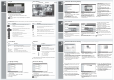
Live Screen
Status Bar
Video Window Quick Menu
Timeline
Status Bar Besides the remote control buttons, you can also use the buttons on the status bar to control NVR.
Item Description
Item Description
Select one of the system setup, search and backup menu items before
accessing it
.
Show the ID of the user who has currently logged in.
Change the screen layout to display both status bar and time line at all times.
Used to select a split mode.
Switch between Auto Sequence and Special Split mode.
Display or hide the OSD menu on the screen.
Move to the PTZ screen. You can control the PTZ operations of
PTZ-com
p
liant camera on the PTZ screen.
Move to the Zoom screen.
Display the log list of the recent recording events.
You can use the camera supporting the audio input to listen the audio.
Select a camera to which the audio signal will be transferred from the
connected microphone.
Start the emergency recording.
Blink when the event occurs. It will not blink if no action to the event has been
set. Click to view information about the event that occured
.
Show the external PC or mobile device that you used to access the network.
Show the disk space information. If you have set the disk overwrite mode, it
will be displayed
“
OW
”
(Over Write) from the start point of the overwriting.
Show the current time.
Item Description
Item Description
Quick Menu Timeline
Dis
p
la
y
the number of the current channel.
Start
p
la
y
in
g
the video of the selected channel from the s
p
ecified time.
Zoom the video of the selected channel.
(
Su
pp
orted later
)
.
Turn on or off the audio si
g
nal of the selected channel.
Turn on or off the micro
p
hone si
g
nal of the selected channel.
Channel No.
Pla
y
Zoom
Sna
p
shot Ca
p
ture
A
udio ON/OFF
Micro
p
hone ON/OFF
Timeline Date
Zoom in/out the
timeline
Navigation
through timeline
Timeline Bar
Display the date of the current timeline.
Click this to select a desired date of the timeline.
Ex
p
and or colla
p
se the timeline.
Move to the previous of next point of time in the timeline.
You can also use the mouse wheel to navigate through
the timeline
Represent the recorded data the color of each bar indicates:
Green : Continuous Recording
Red : Alarm Recording
Blue : Motion Recording
Yellow : Panic Recording
Language Setting Date/Time Setting
Press [SETUP] on remote control, or select <Menu> - <System Setup>
from the status bar.
From <System Setup> - <Display>, select <OSD>
Select a preferred language.
Click <Apply>
1.
2.
3.
4.
1.
2.
3.
4.
Press [SETUP] on remote control, or select <Menu> -
<System Setup>
from the status bar.
From <System Setup> - <System>, select <Date/Time>
Specify the display format of the current time and date.
As the existing data in the same time and date will be deleted if duplicates are found, backup the
existing data for later use.
Click <Apply>.
Getting
Started
Recording
Automatic Recording Setting
Press [MENU] on remote control, and use the
direction buttons to select <RECORD SETUP>
and press [ENTER]
Alternatively, you can select <MENU> - <RECORD
SETUP> from the status bar.
Set <RECORD SETUP MODE> to <AUTO
CONFIGURATION>.
Select “Automatic Record Configuration Mode”.
1.
2.
3.
>ALWAYS HIGH VIDEO QUALITY : Recording will
proceed in the best quality regardless of the event
at all times.
As this option will always make recording in the
best quality, the recording period is the shortest
compared to the other recording mode.
>MOTION RECORD : Recording will proceed only
If a motion is detected.
>ALARM RECORD :
Recording will proceed only
if alarm event occurs.
>MOTION/ALARM RECORD : Recording will
proceed only if a motion is detected or an alarm
event occurs.
>INTENSIVE MOTION RECORD : Normally
recording will be performed in a low quality.
However, the quality will switch to high if a motion
is detected.
>INTENSIVE ALARM RECORD : Normally
recording will be performed in a low quality.
However, the quality will switch to high if an alarm
event occurs.
>INTENSIVE MOTION/ALARM RECORD : Normally
recording will be performed in a low quality.
However, the quality will switch to high if a motion
is detected or an alarm event occurs.
Click <APPLY>.
4.
Time Search
Search
From the <SEARCH> menu, select <TIME
SEARCH>
Specify the search date and time from the calendar
in the left corner of the screen.
You can identify the type of the recording data by
the color in the bar.
1.
2.
3.
>Pink (PRE RECORDING) : The pre-recording is
performed on the recording data after you set the
<PRE RECORDING TIME> from <OPERATION
MODE>.
>Green (Continuous) : The continuous recording is
performed on the recording data.
>Red (Alarm) : The alarm event recording is
performed on the recording data.
>Blue (Motion) : The motion event recording is
performed on the recording data.
>Yellow (Panic) : The panic manual recording is
performed on the recording data
Click to move to desired start time in the time bar,
or use the buttons at the bottom of the status bar to
make search.
Select an item to play and click <PLAY>.
Click to move to desired time, or simply double-click a
desired time in the time bar to play the video data on the
time.
For details on the thumbnail search and event search, refer
to the user manual.
4.
5.
Double-click the time line to move to the Playback mode. Drag and drop it to make backup or
event search for the specified area.
Network
Setting
Network Connection Setting To configure the network settings
Connect the [WAN(UPLINK)] port in the rear panel
of the NVR to any port available except for the WAN
port of the router.
Connect the [WAN(UPLINK] port of the router directly to
the fixed IP LAN cable, or connect it to the xDSL modem.
Check the network address information if using a
network environment connected to the same router.
Enter the network setting menu of the NVR and
provide the IP address.
1.
2.
3.
4.
>IP ADDRESS : 192.168.1.116 (enter the network IP
address.)
>GATEWAY:192.168.1.1 (enter the gateway address)
>SUBNET MASK:255.255.255.0 (type the subnet
mask.)
>The primary, the secondary DNS server:
168.126.63.1 (enter the address of a DNS server.)
1) From the main menu of the NVR, move to <SYSTEM
SETUP> - <NETWORK> - <IP SETUP>.
2) Uncheck the DHCP checkbox and provide the
necessary information manually.
(Check the network address information in the
network environment settings and enter the correct
information.)
Enter an IP address that falls in the privete IP range provided
by the router.
Ex) 192.168.1.2-254, 192.168.0.2-254, 192.168.xxx.2-254
3) When done, configure the port forwarding for RTSP
and Web Service ports by clicking Port Forwarding.
(The default value of the Web service port is 8080.)
4) Click <PORT FORWARDING> for each. You will see
the confirmation message. Click <APPLY> and edit
the menu.
5) The network settings of the NVR are complete.
Some router models may not support UPNP properly.
If you see a failure message after <PORT FORWARDING>
settings, refer to the user manual of the router and configure
the DMZ or port forwarding settings manually.
When done, click <DDNS REGISTRATION TEST>
and <DDNS CONNECTION TEST> in this order.
If you receive a success message, check the NVR
address and click <APPLY> at the bottom.
Check the NVR address and the Web service port in
the network settings to make sure that any Internet-
connected PC can access the NVR.
If you type “mydvr” for the NVR name from DDN
item, the address of the Web viewer is
“http://mydvr.dvrlink.net:8080/
7.
8.
9.
Wh
en
th
e
ne
t
wor
k
con
fi
gura
ti
on
i
s
comp
l
e
t
e,
proceed with the DDNS settings to allow access to
the NVR from outside.
From the main menu of the NVR, move to <SYSTEM
SETUP> - <NETWORK> - <DDNS>.
Rename the NVR, (The default name of the NVR is the
MAC address of the NVR.)
Enter a desired name in combination or characters and
numbers.
5
.
6.