
Data Sheet


GAPTEC-Electronic GmbH & Co. KG
sales@gaptec-electronic.com – www.gaptec-electronic.com
Page 1 of 3
LMS78_0.5R – Rev. 2017-2.5
Specications subject to change without notice.
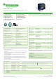
LMS78_0.5R Series
Wide Input Non-Isolated & Regulated, Single Positive/Negative Output
Eciency up to 93%
Operating temperature
range: -40°C ~ +85°C
Pin-out compatible with
LM78XX linears
Short circuit protection (SCP)
Thermal shutdown
Low ripple and noise
Sip package, meet UL94-V0
Low temperature rise
Industry standard pinout
Ultra low no-load power
consumption
Switching Regulator
The LMS78_0.5R series high eciency switching regulators are ideally
suited to replace LM78xx linear regulators and are pin compatible.
Model selection:
LMS78_yy-pp
LM=Series; S=case; ##=Vout; pp=output current
Example:
LMS78_05-0.5R
LM= Series; S= SIP Case; ##= 5Vout; pp=0.5A; R= Revised
Common specications
Short circuit protection: Continuous, automatic recovery
No-load input current: 0.2mA TYP, 1.5mA MAX
Reverse Polarity Input: Forbidden
Input Filter: Capacitor Filter
Temperature rise at full load: 25°C MAX, 15°C TYP
Cooling: Free air convection
Operation temperature range: -40°C~+85°C
Power derating above 71°C
Storage temperature range: -55°C ~+125°C
Pin welding resistance temperature: 260°C MAX, 1.5mm from case for 10 sec
Operating case temperature: 100°C
Storage humidity range: < 95%RH
Package material: Plastic [UL94-V0]
MTBF: >2,000,000 hours
+25°C MIL-HDBK-217F
Weight: 2g
Note:
1. The max. capacitive load should be tested within the input voltage range and
under full load conditions;
2. Without any special statement, all indexes are only specic to positive output
application;
3. Unless otherwise specied, data in this datasheet should be tested under the
conditions of Ta=25°C, humidity<75% when inputting nominal voltage and
outputting rated load;
4. All index testing methods in this datasheet are based on our Company’s
corporate standards;
5. The performance indexes of the product models listed in this manual are as
above, but some indexes of non-standard model products will exceed the
above-mentioned requirements, and please directly contact with our technician
for specic information;
6. Specications subject to change without prior notice.
Output specications
Item Test conditions Min Typ Max Units
Output voltage
accuracy
100% load ±2 ±3 %
Line regulation Input Voltage Range ±0.2 ±0.4 %
Load regulation 10% to 100% load ±0.4 ±0.6 %
Output current limit 3000 mA
Ripple + Noise* 20MHz Bandwidth
Vin=24VDC
0% -100% load
20 75 mVp-
p
Over heat protec-
tion
Internal IC junction 170 °C
Short circuit input
power
0.5 1.8 W
Switching frequency 550 850 KHz
Transient response
deviation
Nominal input, 25%
load step change
55 250 mV
Transient recovery
time
Nominal input, 25%
load step change
0.5 2 ms
Temperature coef-
cient
-40 °C to +85 °C
ambient
0.03 %/°C
* Test ripple and noise by “parallel cable” method. With the load lower than 10%,
maximum ripple and noise will be 150mVp-p.
EMC specications
EMI CE CISPR22/EN55022 CLASS B (External circuit refer to EMC recommended circuit, 2 or EMC module application circuit)
EMI RE CISPR22/EN55022 CLASS B (External circuit refer to EMC recommended circuit, 2 or EMC module application circuit)
EMS ESD IEC/EN61000-4-2 Contact ±4KV perf. Criteria B
EMS RS IEC/EN61000-4-3 10V/m perf. Criteria A
EMS EFT IEC/EN61000-4-4 ±2KV perf. Criteria B (External circuit refer to EMC recommended circuit, 1 )
EMS CS IEC/EN61000-4-6 3 Vr.m.s perf. Criteria A
EMS Voltage dips,
short and
interruptions
immunity
IEC/EN61000-4-29 0%-70% perf. Criteria B