
Data Sheet


GAPTEC-Electronic GmbH & Co. KG
sales@gaptec-electronic.com – www.gaptec-electronic.com
Page 3 of 6
LEDT16_24 – Rev. 2015-1.0
Specifications subject to change without notice.
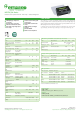
LEDT16_24 Series
Constant current power LED driver - Wide Input - Isolated & Regulated
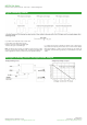
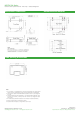
Digital dimming control
Analogue dimming control and application sample
Io_set refers to the expected output current value.
Io_norm refers to the rated output current
D refers to the pulse width of the PWM signal
T refers to the cycle of the PWM signal
Note: The formula only supplies as a reference, and the output current
may be a little deviation with different load. The Ton(min) of PWM signal
must be greater than 0.7ms, or the driver can’t be operated normally.
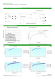
It is natural for the driver to generate an audibly noise in dimming pro-
cess, because the frequency of the control circuit is within human audibly
range (20Hz~20KHz). In order to avoid the human eye can observe the
LED flashes, the PWM dimming frequency is recommended to set above
100Hz.
Analogue dimming circuit Analogue input voltage vs. output