-08 ATOgRegator.com ra 888w-G ww.ga BY V-BRO PRODUCTS RESIDENTIAL MOTORIZED STORAGE UNIT Model: INSTALLATION, OPERATING, AND SAFETY INSTRUCTIONS Distributed Exclusively by: V- BRO PRODUCTS, LLC www.garagegator.com For technical questions and replacement parts, Please call 1-888-GATOR-08 -- Local: 352-609-7025 YouTube installation videos can be found at: www.garagegator.
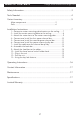
TABLE OF CONTENTS Garage Gator Motorized Storage Unit Safety Information .....................................................................................3 Tools Needed............................................................................................4 Carton Inventory .......................................................................................5 Major components ......................................................... 5 Parts .......................................................
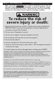
SAFETY INFORMATION Garage Gator Motorized Storage Unit When you see the WARNING safety symbol on the following pages this will alert you of the possibility of serious injuries or death if you do not comply with the corresponding instructions. The hazard may come from something mechanical or from electric shock. Read the instructions carefully! To reduce the risk of severe injury or death: 1. READ AND FOLLOW ALL SAFETY, INSTALLATION AND OPERATION INSTRUCTIONS.
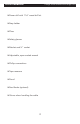
TOOLS NEEDED Garage Gator Motorized Storage Unit Power drill with 1 16” wood drill bit Step ladder Pliers Safety glasses Ratchet and ½” socket Adjustable, open ended wrench Phillips screwdriver Tape measure Pencil Stud finder (optional) Gloves when handling the cable 4
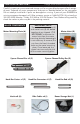
CARTON INVENTORY Garage Gator Motorized Storage Unit Carefully inspect your new motorized storage unit for any possible damage and/or shortage of parts. Separate all major components and parts as detailed below on the next page. Do not attempt installation if parts are damaged or missing. If parts of your are missing or appear damaged, call V-Bro customer service at 1-888-GATOR- 08, or ocally at 352-343-5438, Monday - Friday, 9:00 AM to 5:00 PM Eastern Time.
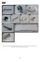
PARTS K L 3” Lag bolt x12 N M 5/16” nut x4 (shipped attached to part A) O power cord cable clamps x2 R hand control switch holder hook x1 P 2” wood screws x2 Q ¼” X ½” bolt x2 6mm nut x3 S ¾” hole saw drill bit x1 paper motor mounting template x1 T 13mm socket x1 Drawings & photos for illustrative purposes only – actual parts may vary from those pictured. Parts are not shown actual size.
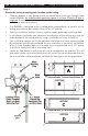
INSTALLATION INSTRUCTIONS Garage Gator Motorized Storage Unit Step 1 Determine motor mounting plate location on the ceiling Choose a location in your garage where you would like to install your Garage Gator model . An unobstructed operating space of at least 3 feet by 9 feet is required. The motor mounting plate (A) should be installed at least 3 feet away from walls or any other obstructions.
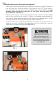
Step 2 Install the motor mounting plate to the ceiling • Position the paper motor mounting template (S) in the installation area and mark with a pencil the four locations where the lag bolts will be fastened. • It is very important that the lag bolts are fastened to the center of the joists. Use the hole saw drill bit (R) or cut away the drywall with a utility knife to obtain an unobstructed view of the width of the joists so the exact center can easily be determined (covered ceilings only).
Step 3 Attach the motor hoist to the motor mounting plate. • Identify your installation option by referring to the illustrations on page 7. Determine how the motor hoist should be rotated – which direction the 4 1/2” spacer channel bar attachment tab should be pointing. Ensure your motor hoist is rotated properly before placing the motor hoist on the motor mounting plate.
Step 4 Connect and install the first spacer channel bar • Press the spacer channel bar flush with the ceiling and mark with a pencil where a lag bolt will be used to attach the bar to the joist. – Perpendicular joist installation (option A or B on page 7). Make a mark at either the 16” hole or 24” hole depending on your joist spacing. Remove the spacer channel bar. – Parallel joist installation (option C or D on page 7). Make a mark at the 21” hole. Remove the spacer channel bar.
Step 5 Connect and install the second spacer channel bar • Line up the hole in the flared end (the end without a fixed nut) of the spacer channel bar (C) over the hole in the installed spacer channel pulley bar. Thread a 1/4” x 1/2” bolt (P) into the hole and finger tighten. (SEE FIG. 5) • Press the spacer channel bar flush with the ceiling and mark with a pencil where the lag bolt(s) will be used to attach the bar to the joist(s). – Perpendicular joist installation (option A or B on page 7).
Step 6 Connect and install the spacer channel pulley bar • Press the spacer channel bar flush with the ceiling and mark with a pencil where the lag bolts will be used to attach the bar to the joist. – Perpendicular joist installation (option A or B on page 7). There are sets of holes on each side of the spacer channel bar at 16” and 24” from the last lag bolt installed. Measure from the last lag bolt and determine the appropriate holes depending on your joist spacing. Remove the spacer channel pulley bar.
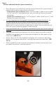
Step 7 Install the cable over the channel bar pulley • Plug in the motor hoist (B) to the nearest 110 volt power outlet. • Use the hand control switch and safely lower the cables until 9 feet of cable is visible. • Unplug the power cord from the outlet. • Temporarily remove the pulley at the end of the spacer channel pulley bar (D). (use pliers to remove the cotter pin then remove the clevis pin to release the pulley) (SEE FIG.
Step 8 Assemble the hook bar • Assemble the three middle pieces of the hook bar by lining up the spring clips from the hook bar center (E) to the holes of the hook bar connectors (F). (SEE FIG. 8A) • Slide hooks (H) and bike cables (I) onto the assembled piece. (SEE FIG. 8B & 8C) • Attach each hook bar end (G) to the assembled middle section by lining up the slotted holes from the hook bar end to the holes of the hook bar connectors. (SEE FIG.
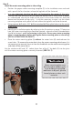
Step 10 Install the hand control switch holder hook • Secure the hand control switch holder hook (M) to a convenient location on the closest appropriate wall by removing the protective paper from the adhesive strip then adhere the hook to the wall by applying pressure with your fingers. (SEE FIG. 10) FIG. 10 Step 11 FIG. 10A Plug in the unit • Plug in the motor hoist (B) to the nearest 110 volt power outlet.
OPERATING INSTRUCTIONS Garage Gator Motorized Storage Unit TO RAISE OR LOWER THE HOOK BAR: • **Do not stand under the lift. • Turn the key in the hand control switch to the “ON” position. • Press and hold the rocker switch in the direction you want the hook bar to travel. • Release the switch when desired location is reached. TO LOAD THE HOOK BAR: FIG. 13 • Lower the hook bar to a comfortable height. • **Evenly distribute the weight of articles stored.
CONTACT INFORMATION Garage Gator Motorized Storage Unit V-Bro Products is on call. Installation and service information as well as ordering repair parts is as near as your telephone Monday - Friday 9:00 AM to 5:00 PM Eastern Time (subject to holidays). Contact us toll free. V-Bro Products 28114 County Road 561 Tavares, Florida 32778 888-428-86708 Local: 352-343-0702 fax: 352-742-0702 email: info@garagegator.
LIMITED WARRANTY What is covered: Any defect in material and workmanship from personal, normal household use in accordance with the Owner’s Manual. For how long: One year from date of purchase. Who gets the warranty: The warranty is limited to the consumer who originally purchased the product. Geographic scope: This warranty applies only to the Residential Motorized Storage Unit purchased in the United States and Canada.