PATIO HEATER Owner’s Manual GS4400SS GS4400GN GS4400BK GS4400CP GS4400GD GS4400WH IMPORTANT Read this manual carefully before assembling, using or servcing this heater keep this manual for future reference. R R CSA International Requirement NO.5.90.
Contents DANGER General Safety Information....................................... 1 Assembly Instructions DANGER indicates an imminently hazardous situation which, if not avoided, will result in death or serious injury. Components & Hardware........................................ 3 Additional Requirements ........................................ 3 WARNING Installation Process Step1 - Attach Wheel Assembly to Base.................
DANGER DANGER • EXPLOSION - FIRE HAZARD • Keep solid combustibles, such as building materials, paper or cardboard, a safe distance away from the heater as recommended by the instructions. • Provide adequate clearances around air openings into the combustion chamber. • Never use the heater in spaces which do or may contain volatile or airborne combustibles, or products such as gasoline, solvents, paint thinner, dust particles or unknown chemicals.
WARNING • This product is fueled by propane gas. Propane gas is invisible, odorless, and flammable. An odorant is normally Assembly Instructions Components Remove all components from package. added to help detect leaks and can be described as a “rotten egg” smell. The odorant can fade over time so leaking gas is not always detectable by smell alone. • Propane gas is heavier than air and leaking propane will sink to the lowest level possible.
Hardware (GS4400-P4) Picture Installation process Qty Description Used in Step(s) 6 Large Bolt 4 5 Medium Bolt 1&3 4 Small Bolt 4 Large Screw 2 9 Small Screw 8 Large Flat 9 Washer Small Flat 9 2 6 Washer Large Flange Nut Small Flange Nut (For models without . . Wheels , skip to Step 2) Step 1 – Attach Wheel Assembly to Base Line up holes in Wheel Bracket with corresponding holes in Base, Insert 2 Medium Bolts through holes, finger tighten 2 Large Flange Nuts.
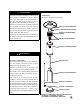
. . . Lay Bucket inside of Base and screw on large nut. Tighten with Philips screwdriver. .. Step 5 – Load Cylinder Housing onto Post Load Cylinder Housing onto Post. Slide Cylinder Housing down. For improve the stability , please fill the bucket with Sand. Step 3 – Attach Support Brackets to Base Attach three Support Brackets loosely to Base with three medium bolts downward through Support Brackets into the Base. 3 Req’d Medium Bolts .. Step 6 – Attach Reflector Studs to Screen Cover ..
.. . Load Head Assembly by inserting hose into post. Insert Head Assembly into post. 9 Req’d Small Screw s Control knob should be above decal on post. . 9 Req’d Small Flat Washers . . 9 Req’d Cap Nuts Slide one Small Flat Washer over threaded end of screw and screw on Cap Nut loosely. Attach Head Assembly to post, and loosely install four small bolts. Tighten bolts securely. (For models with Entire Reflector , skip to Step 9) . .
.. Step 9 – Attach Reflector Assembly to Studs Support Heater. Slide 3 Large Flat Washers over threaded end of Studs. 6 Req’d Large Flat Washers .. . . 3 Req’d Wing Nuts Locate Reflector Assembly on 3 studs. Install large flat washers on studs & securely tighten wing nuts but do not over-tighten! Step 10 – Connect Hose & Regulator to Cylinder You must propane provide gas and propane cylinder. Use a standard 20 lb. propane cylinder only. . . . . .. .. .
Leak Check Operation WARNING DANGER • Perform all leak tests outdoors. • Extinguish all open flames. • CARBON MONOXIDE HAZARD • NEVER leak test when smoking. • Do not use the heater until all connections have been leak • For outdoor use only. Never use inside house, or other tested and do not leak. unventilated or enclosed areas. This heater consumes air (oxygen). Do not use in unventilated or enclosed areas to avoid endangering your life. DANGER • EXPLOSION - FIRE HAZARD . . . .. .. .
. . .. .. . . . Your heater was designed and approved for outdoor 4 is visible through Viewing Hole. use only. Do NOT use it inside a building, garage, or any other enclosed area. 5 Release Control Knob after 30-60 seconds. Pilot Light will remain lit. If not, return to step 1. Make sure surrounding areas are free of combustible materials, gasoline, and other flammable vapors or Push and release the Igniter button until pilot flame 6 Turn Control Knob to “PILOT”. Main Burner will light liquids.
If you experience any ignition problem please consult “Troubleshooting” on page 11. Caution: Avoid inhaling fumes emitted from the heater’s first use. Smoke and odor from the burning of oils used in manufacturing will appear. Both smoke and odor will dissipate after approximately 30 minutes. The heater should NOT produce thick black smoke. Note: The burner may be noisy when initially turned on. To . . . Shut Down: Turn Control Knob clockwise to Pilot.
Troubleshooting If the problem is: And this condition exists: Then do this Cylinder valve is closed Open valve Blockage in orifice or pilot tube Clean or replace orifice or pilot tube Open gas line and bleed it (pressing control Pilot won’t light Air in gas line knob in) for not more than 1 - 2 minutes or until you smell gas Low gas pressure with cylinder valve Note: Heater operates at reduced efficiency below 40ºF fully open Clean dirt from around pilot Connection between gas valve and Ti
.. .. . . Gas odor with extreme yellow tipping of flame. Heater does NOT reach the desired temperature. Heater glow is excessively uneven. Heater makes popping noises. Ґ . . . Store heater upright in an area sheltered from direct contact with inclement weather (such as rain, sleet, hail, snow, dust and debris). If desired, cover heater to protect exterior surfaces and to help prevent build up in air passages. Never leave LP cylinder exposed to direct sunlight or excessive heat.