
Installation Guide


10
ASSEMBLY INSTRUCTIONS
Hardware Used
GG
KK
12. Screw gas hose and regulator (E) onto propane
cylinder (not included). Do not cross-thread.
Place the propane cylinder into the cylinder housing (F ),
fasten cylinder with propane tank strap, then close the door.
The propane gas and cylinder are sold separately.
Use a standard 20 lb. propane cylinder only
(approximately 12.2 in./31cm in diameter and 17.9 in.
/45.5cm high). Use this heater only with a propane vapor
withdrawal supply system. See chapter 5 of the standard
for storage and handling of liquefied petroleum gas,
ANS/NFPA 58. Your local library or f
ire department
should have this book. Storage of an appliance indoors is
permissible only if the cylinder is disconnected and
removed from the appliance. A cylinder must be stored
outdoors in a well-ventilated area out of the reach of
children. A disconnected cylinder must have dust caps
tightly installed and must not be stored in a building,
garage or any other enclosed area. The maximum inlet
gas supply pressure: 250 psi/1750 kPa. The minimum
inlet gas supply pressure: 5 psi/35kPa. Manifold
pressure with regulator provided: 11 inch W.C/2.74 kPa.
The pressure regulator and hose assembly supplied with
the appliance must be used. The installation must conform
with local codes, or in the absence of local codes,with
national fuel gas code, ANS Z223.1/NFPA54, natural gas
and propane Installation Code, CSA B149.1, or propane
storage and handling code, B149.2.
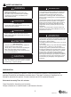
11. Slide Φ8 washers (GG) over the threaded ends of
reflectors spacers (FF). Attach reflector assembly to head
assembly (C). Place Φ8 washers (GG) over threaded ends
of reflector spacers (FF) sticking out through reflector
assembly and secure with wing nuts (KK).
Note: Do not overtighten.
x 6
Φ8 Washer
x 3
Wing Nut
FF
x 3
Reflector Spacer
11
12
KK
GG
C
FF
KK
GG
F
J
E
Lowes.com
R