ITEM #0574424 GAS PATIO HEATER MODEL #PG167H-A Français p. 21 Español p. 42 Garden Treasures® is a registered trademark of LF, LLC. All Rights Reserved. ATTACH YOUR RECEIPT HERE Serial Number Purchase Date Questions, problems, missing parts? Before returning to your retailer, call our customer service department at 1-800-643-0067, 8 a.m. - 8 p.m., EST, Monday - Friday.
TABLE OF CONTENTS Product Specifications…….....................................................................................................3 Package Contents……...........................................................................................................4 Hardware Contents…….........................................................................................................5 Preparation……....………..............................................................................................
PRODUCT SPECIFICATIONS Certification Height Overall Reflector Diameter Rated Heat Input Fuel Gas Supply Manifold Pressure Injector Size (Diameter) Safety Features Gas Supply Pressure CSA 86.6 inches 31.5 inches 45,000 BTU/HR Propane-LP 20-Lb LP-Gas Cylinder 11 inches W.C. 2.
PACKAGE CONTENTS A B C D E F G H N I O J P K Q L R M PART A DESCRIPTION Top Dome QUANTITY 1 PART K DESCRIPTION Screw Sheath QUANTITY 2 B C KD Dome Burner Assembly 4 1 L M Door Handle Bezel Door Handle 2 1 D E F G Pole Assembly Deck Ring Table Table Support Bracket 1 1 1 2 N O P Q Rear Panel Right Panel Assembly Tank Holder Door Beam 1 1 1 1 H I Table Rack Left Panel Assembly 1 1 R S Base Assembly Cover 1 1 J Door Assembly 1 4
HARDWARE CONTENTS AA M6 x 16 mm Bolt Qty. 20 BB M6 Washer Qty. 4 GG HH M5 x 8 mm Bolt Qty. 15 M5 Nut Qty. 12 CC M6 Spring Washer Qty. 4 DD M6 x 30 mm Bolt Qty. 4 II M5 Washer Qty. 12 JJ Reflector Spacer Qty. 3 EE M6 Nut Qty. 4 FF Battery Qty. 1 KK Wing Nut Qty. 3 PREPARATION Before beginning assembly of product, make sure all parts are present. Compare parts with package contents list and hardware contents list.
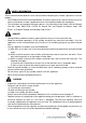
SAFETY INFORMATION Please read and understand this entire manual before attempting to assemble, operate or install the product. · CALIFORNIA PROPOSITION 65 WARNING: Chemicals known to the state of California to cause cancer, birth defects or other reproductive harm are created by combustion of propane. · The installation must conform with local codes or, in the absence of local codes, with the National Fuel Gas Code, ANSI Z223.1 /NFPA 54, Natural Gas and Propane Installation Code, CSA B149.
· · · · · · · · · · SAFETY INFORMATION The cylinder used must include a collar to protect the cylinder valve. Installation and repair should be done by qualified service person; the heater should be inspected before use and at least annually by a qualified service person. Do not obstruct the flow of combustion and ventilation air. The LP-gas supply cylinder to be used must be: (a) Constructed and marked in accordance with the Specifications for LP-gas cylinders of the U.S.
ASSEMBLY INSTRUCTIONS 1. Attach left panel assembly (I) to base assembly (R) using M6 x 16 mm bolts (AA). Note: Do not tighten M6 x 16 mm bolt (AA) completely until after sliding the left panel assembly (I) enough that the bolt rests in the narrow end of the keyslot. 1 O I R Repeat this side for right panel assembly (O). Hardware Used AA x 16 mm Bolt AA M6 M6X10 Bolt 4 xX 4 2. Attach rear panel (N) to left panel assembly (I) and right panel assembly (O) using M6 x 16 mm bolts (AA).
ASSEMBLY INSTRUCTIONS 4. Attach door handle bezel (L) on both sides of the door handle (M). Insert screw sheaths (K) into the holes on the backside of door assembly (J). Then, attach door handle assembly to door assembly (J) using M6 x 16 mm bolts (AA) through the screw sheaths (K) and into the preassembled door handle bezels (L) on door handle (M). 4 M L M L K AA Hardware Used x 16 mm Bolt AA M6 M6X10 Bolt J Xx 22 5.
ASSEMBLY INSTRUCTIONS 7. Open door assembly (J). Then, from inside, secure pole assembly (D) to table rack (H) using M6 x 30 mm bolts (DD), M6 washers (BB), M6 spring washers (CC) and M6 nuts (EE). 7 D DD H Hardware Used J M6 Washer Washer 18X6.5X1.5 BB M6 BB X4 x4 CC StretchyWasher Washer CC M6M6Spring xX44 M6 x X 30mm 30 mmBolt DD M6 xX44 nuts M6 Nut EE M6 xX44 EE 8. Remove the bolts and washers preassembled underneath the table (F).
ASSEMBLY INSTRUCTIONS 9. Insert the deck ring (E) over the pole assembly (D) so it rests on top of table (F). E 9 D F 10. From inside the cabinet, secure the left end of the tank holder (P) into the holder preassembled on left panel assembly (O). Then lock the other end of the tank holder (P) into the holder on right panel assembly (I). Note: The tank holder (P) is highly recommended to be installed as it can prevent a gas tank from shaking.
ASSEMBLY INSTRUCTIONS 11. Insert reflector spacers (JJ) into the top of burner assembly (C). JJ 11 C 12. Thread the regulator assembly preassembled to burner assembly (C) through the pole assembly (D). Once the burner assembly (C) rests on pole assembly (D), secure with M5 x 8 mm bolts (GG).
ASSEMBLY INSTRUCTIONS 13. Attach KD domes (B) using M5 x 8 mm bolts (GG), M5 nuts (HH) and M5 washers (II). Then, complete dome assembly by attaching top dome (A) to KD domes (B) with M5 x 8 mm bolts (GG), M5 nuts (HH) and M5 washers (II). 13 B HH II Hardware Used GG GG M5 X x 88mm M5 mmBolt Bolt xX12 12 HH M5 Nut M5 Nut xX12 12 5M5 mm Washer Washer xX12 12 II HH A II GG 14. Attach dome assembly to burner assembly (C) by securing wing nuts (KK) to reflector Hardware Used spacers (JJ).
ASSEMBLY INSTRUCTIONS 15. To install the battery (FF), unscrew the igniter cap preassembled to burner assembly (C). Insert battery (FF) into the igniter, ensuring the positive "+" end faces outward. Then replace the igniter cap. 15 Igniter Igniter 16. Connect the preassembled regulator assembly from burner assembly (C) to a 20-lb. LP-gas cylinder (sold separately). Line up threads on cylinder fitting with those on regulator and rotate clockwise until tight. HAND TIGHTEN ONLY.
OPERATING INSTRUCTIONS Checking for Leaks a. Make leakage solution by mixing 1-part liquid dish soap and 3-parts water. b. Spoon or brush several drops (or use squirt bottle) of the solution onto the gas hose/regulator and regulator/cylinder and hose connections. c. Turn on gas cylinder valve. Inspect the connections and look for bubbles. 1. If no bubbles appear, the connection is safe. 2. If bubbles appear, there is leakage. Loosen and re-tighten this connection.
OPERATING INSTRUCTIONS In any case of failure of normal ignition, please use the ignition bar with a match to reach the burner for ignition through the hole on the bottom of burner diffuser. Insert the match from the back side of the burner assembly where is opposite to the control panel. 2 WARNING If at any time you are unable to light burner and smell gas, wait 5 minutes to allow gas to dissipate before attempting to light heater. WARNING DO NOT touch or move heater for at least 45 minutes after use.
CARE AND MAINTENANCE Cleaning · Wipe surfaces clean with mild dish detergent or baking soda. · For stubborn surfaces use a citrus-based degreaser and a nylon scrubbing brush. · Rinse clean with water. Note: While cleaning the unit, be sure to keep the area around the burner dry at all times. Do not submerge the control valve assembly. If the gas control is submerged in water, do NOT use it. It must be replaced. TIP: Use high-quality automobile wax to help maintain the appearance of the heater.
TROUBLESHOOTING PROBLEM Burner doesn’t light. POSSIBLE CAUSE 1. Gas pressure is low. 2. The orifice is blocked. 3. Control knob is not in “ON” position. 1. Gas pressure is low. 2. The control knob is not positioned at “High”. 3. The burner jet is partially blocked. 4. Outdoor temperature is less than 40°F and/or tank is less than 1/4 full. 5. Supply hose is bent or kinked. CORRECTIVE ACTION 1. Turn the gas cylinder valve “OFF” and replace the cylinder. 2. Clear blockage. 3. Turn control knob to “ON” 1.
REPLACEMENT PARTS LIST For replacement parts, call our customer service department at 1-800-643-0067, 8 a.m. - 8 p.m.
REPLACEMENT PARTS LIST PART DESCRIPTION PART # PART DESCRIPTION PART # 1 2 3 Top Dome KD Dome Burner Chamber Assembly 17 18 19 Door Handle Bezel Door Handle Rear Panel 2406488 5015240 5203093 4 Burner Assembly 20 Right Panel 5203092 5 6 7 8 9 10 11 12 13 14 Knob Valve Shroud Cover Igniter Pole Assembly Deck Ring Granite Table Table Support Bracket Table Rack Left Panel Assembly Spring Sheath 21 22 23 24 25 26 27 28 29 30 Tank Holder Door Beam Magnet Base Base Support Wheel Wheel Support T