
Quick Start Guide

1. Main switch
2. STOP button
3. LED for function check of the
boundary and guide wires
4. Cutting height indication
5. Display
6. Keypad
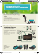
3. Connecting the boundary wire
See chapter 3.5 in the Operator’s Manual
1. Open the connector and lay the wire ends in the recesses on each connector.
2. Press the connectors together using a pair of pliers.
3. Cut off any surplus boundary wire. Cut 1 to 2 cm above the connectors.
4. Press the connectors onto the contact pins, marked A, on the charging station. It is
important that the right-hand wire is connected to the right-hand contact pin, and the
left-hand wire to the left-hand pin.
5. Mark the wires with the accompanying cable markers. This makes it easier to reconnect
the wires correctly.
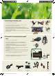
4. Placement of and connecting the guide
wire
See chapter 3.6 in the Operator’s Manual
1. Run the guide wire through the slot at the bottom of the charging station.
2. Fit the connector to the guide wire in the same way as for the boundary wire,
according to the instructions above.
3. Fasten the connector to the contact pin marked Guide on the charging station.
4. Lay the guide wire at least 2 metres straight out from the front edge of the
charging station.
5. Run the guide wire to the point on the boundary loop the connection will be made.
Avoid laying the wire at tight angles.
6. Cut the boundary wire with a wire cutters at the centre of the eyelet that was made
in point 2.3.
7. Connect the guide wire to the boundary wire using the accompanying couplers.
Press the couplers completely together with a pair of pliers.
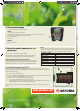
As a complement to this Quick Guide, there are step by step installation movies
available on the GARDENA website, www.gardena.com
Power supply Low voltage cable Boundary wire and
couplers
Staples Connectors Measurement
gauge
1
7
4
2 3
min 2 m / 7 ft
1
1
4
5
1157872-26,QG,R38Li,R40Li,R45Li,R50Li,R70Li,GB.indd 11 2015-12-04 11.02