Operator‘s manual SILENO+ R160Li/LiC gardena.com InDesign_P15G_omslag_A5.
Contents 1 Introduction 1.1 Support.......................................................3 1.2 Product description.....................................3 1.3 Product overview........................................4 1.4 Symbols on the product..............................5 1.5 Symbols on the display.............................. 6 1.6 Symbols on the battery...............................6 1.7 Menu structure overview 1......................... 7 1.8 Menu structure overview 2......................... 8 1.
1 Introduction Serial number: PIN code: Product registration key: The serial number is on the product rating plate and on the product carton. • Use the serial number to register your product on www.gardena.com. 1.1 Support For support about the GARDENA product, speak to your GARDENA central service. 1.2 Product description Note: GARDENA regularly updates the appearance and function of the products. Refer to Support on page 3. automatically. Collection of grass is not necessary.
1.3 Product overview 3 4 1 9 2 8 7 5 10 6 19 14 12 18 11 13 33 28 20 27 21 15 16 17 32 30 22 25 26 29 24 23 31 The numbers in the figure represent: 1. 2. 3. 4. 5. 6. 7. 8. 9. 10. 11. 12. 13. Body Hatch to cutting height adjustment Hatch to display and keypad Stop button Rear wheels Front wheels Cutting height adjustment Contact strips LED for operation check of the charging station and boundary wire Charging station Rating plate Display Keypad 4 - Introduction 34 14.
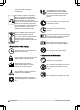
26. Measurement gauge for help when installing the boundary wire (the measurement gauge is broken loose from the box) 27. Operator’s Manual and Quick Guide 28. Extra blades 29. Low voltage cable 30. Alarm decal 31. USB cable for Software-Updates 32. smart Gateway (only for GARDENA R160LiC) 33. smart Gateway LAN-cable (only for GARDENA R160LiC) 34. smart Gateway Power Supply (only for GARDENA R160LiC) 1.4 Symbols on the product These symbols can be found on the product. Study them carefully.
accordance with local legal requirements. The chassis contains components which are sensitive to electrostatic discharge (ESD). The chassis must also be resealed in a professional manner. For these reasons the chassis shall only be opened by authorized service technicians. A broken seal can result in the entire or parts of the guarantee no longer being valid. The low voltage cable must not be shortened, extended or spliced. Do not use a trimmer nearby the low voltage cable.
1.7 Menu structure overview 1 Timer Overview/Monday Period 1 All Mo days Period 2 Tu We Th Copy Fr Sa Reset Su Current day All week SensorControl* Cutting time On/Off Low Medium High smart system** Exclude device Status Connected Yes/No Signal strength Good Poor Bad Security Advanced Security level Low Medium High New loop signal Change PIN code * GARDENA R160Li, R160LiC ** GARDENA R160LiC 1025 - 001 - 23.01.
1.8 Menu structure overview 2 Installation Lawn coverage Advanced Area 1-3 How? How far? How often? Disable More Test Reset Corridor width Exit angles Reversing distance Drive past wire Settings ECO mode General On/Off 8 - Introduction Time & date Language Set time Set date Country Time format Reset all user setting About Date format 1025 - 001 - 23.01.
1.9 Display The display on the product shows information and settings of the product. To access the display, push the STOP button. 1.10 Keypad The keypad on the product let the operator navigate in the menu of the product. To access the keypad, push the STOP button. 3 2 1 4 5 6 7 1. 2. 3. 4. 5. 6. 7. The START button is used to start the operation of the product. The BACK button is used when moving back up in the menu lists. The arrow buttons are used to navigate in the menu.
2 Safety 2.1 Safety definitions 2.2 General safety instructions Warnings, cautions and notes are used to point out specially important parts of the manual. The following system is used in the Operator’s Manual to make it easier to use: WARNING: Used if there is a risk of injury or death for the operator or bystanders if the instructions in the manual are not obeyed.
2.2.1 IMPORTANT. READ CAREFULLY BEFORE USE. KEEP FOR FUTURE REFERENCE The operator is responsible for accidents or hazards occurring to other people or property. This appliance is not intended for use by persons (including children) with reduced physical, sensory or mental capabilities (that could affect a safe handling of the product), or lack of experience and knowledge, unless they have been given supervision or instruction concerning use of the appliance by a person responsible for their safety.
WARNING: The product can be dangerous if used incorrectly. WARNING: Do not use the product when persons, especially children, or animals, are in the work area. WARNING: Keep your hands and feet away from the rotating blades. Never put your hands or feet close to or under the product when the motor is running. 2.
• • • • • • • • • • • • • Start the product according to the instructions. When the main switch is set to 1; make sure to keep your hands and feet away from the rotating blades. Never put your hands and feet under the product. Never touch moving hazardous parts, such as the blade disc, before it has come to a complete stop. Never lift up the product or carry it around when the main switch is in position 1. The product must never be allowed to collide with persons or other living creatures.
2.3.5 In the event of a thunderstorm CAUTION: Do not lift the product when it is parked in the charging station. It can damage the charging station and/or the product. Press the STOP button and pull the product out of the charging station before lifting it. 2.3.4 Maintenance WARNING: When the product is turned upside down the main switch must always be in the 0 position. The main switch should be set in the 0 position before all work on the chassis of the product, such as cleaning or replacing the blades.
3 Installation 3.1 Introduction - Installation WARNING: Read and understand the safety chapter before you install the product. CAUTION: Only use original spare parts and installation material. 3.3.1 To examine where to put the charging station • • • • Keep a minimum 3 m / 5 ft. of free space in front of the charging station. Keep a minimum of 1.5 m / 5 ft. of free space to the right and to the left of the charging station. Put the charging station near an outdoor power outlet.
3.3.2 To examine where to put the power supply • • • E C WARNING: Do not change the power supply. Do not cut or extend the lowvoltage cable. There is a risk of electrical shock. A Low-voltage cables of different lengths are available as accessories. CAUTION: Make sure that the blades on the product do not cut the lowvoltage cable. CAUTION: Do not put the low-voltage cable in a coil or below the charging station plate. The coil causes interference with the signal from the charging station.
CAUTION: Do not make sharp bends when you install the boundary wire. CAUTION: For careful operation without noise, isolate all obstacles such as trees, roots and stones. 0 cm / 0" 3.3.3.1 To put the boundary wire in a slope • • • For slopes steeper than 35% inside the work area, isolate the slope with boundary wire. For slopes steeper than 15% along the outer edge of the lawn, put the boundary wire 20 cm / 8 in. (A) from the edge.
B A Note: When the product cuts grass in the secondary area, the Secondary area mode must be selected. Refer to Secondary area on page 28. 3.3.4 To examine where to put the guide wire • • • • • Put the guide wire in a line at a minimum of 2 m / 7 ft. in front of the charging station. Make sure that the guide wire has as much free area as possible to the left of the guide wire when facing the charging station. Refer to To set the corridor width of the guide wire on page 18.
3.4 Installation of the product 3.3.5 Work area examples 3.4.1 To install the charging station WARNING: Obey national regulations about electrical safety. D 1. A 2. 3. 4. B Read and understand the instructions about the charging station. Refer to To examine where to put the charging station on page 15. Put the charging station in the selected area. Connect the low-voltage cable to the charging station. Put the power supply at a minimum height of 30 cm / 12 in.
6. 7. 8. Attach the low-voltage cable in the ground with stakes or bury the cable. Refer to To put the wire into position with stakes on page 21 or To bury the boundary wire or the guide wire on page 21. Connect the wires to the charging station. Refer to To install the boundary wire on page 20 and To install the guide wire on page 20. Attach the charging station to the ground with the supplied screws. CAUTION: Do not make new holes in the charging station plate.
CAUTION: Twinned cables, or a screw terminal block that is insulated with insulation tape are not satisfactory splices. Soil moisture will cause the wire to oxidize and after a time result in a broken circuit. 4. Put the boundary wire or the guide wire into position. Refer to To put the wire into position with stakes on page 21 or To bury the boundary wire or the guide wire on page 21. 3.
3.9.2 To do the basic settings Before you start the product for the first time, you must do the basic settings and calibrate the product. 1. Push the STOP button. 2. Set the Main switch to 1. 3. Push the arrow buttons and the OK button. Select language, country, date, time and set a PIN code. Note: It is not possible to use 0000 as PIN code. 4. Put the product in the charging station. 5. Push the START button and close the hatch.
• Time lock - The product locks if the PINcode has not been entered in 30 days. Enter the PIN-code to get access to the product. 3.10.3.1 To set the security level Select 1 of 3 security levels for your product. 1. 3.10.2.4 To reset the timer setting You can remove all timer settings and use the factory setting. The factory timer setting lets the product to operate all hours of each day of the week. Refer to Timer and Standby on page 29. 1. Do steps 1–3 in To get access to the menu on page 22. 2.
3.10.4.1 To set the SensorControl 1. Do steps 1–3 in To get access to the menu on page 22. 2. Use the arrow buttons and the OK button to move through the menu structure SensorControl > Use SensorControl. 3. Push the OK button to select the SensorControl. 4. Push the BACK button. 7. a) b) c) 3.10.4.2 To set the SensorControl frequency Do steps 1–3 in To get access to the menu on page 22. 2. Use the arrow buttons and the OK button to move through the menu structure SensorControl > Cutting time.
6. Use the arrow buttons and the OK button to move through the menu structure Installation > Lawn Coverage > Area 1-3 > More > Test. 7. Push the OK button. 8. Push the START button and close the hatch. 9. Push the STOP button when the product is at the distance you select to measure. The distance shows in the display. 3.10.5.4 To disable the Lawn Coverage function Disable the Lawn Coverage function for each area. 1. 2. 3. 4. 5. Do steps 1–3 in To get access to the menu on page 22.
Note: Push the STOP button before you remove the product from the charging station. If not, the product can not be started in the work area. Note: Security level, PIN code, Loop signal, Messages, Date & Time, Language and Country settings are not reset. 3.10.9.2 To set the time & date 3.10.9.6 The About menu 1. Do steps 1–3 in To get access to the menu on page 22. 2. Use the arrow buttons and the OK button to move through the menu structure Settings > General > Time & Date. 3.
4. The inclusion code is presented in the product display. Note: The product can only be shown as a device in the smart system app if it first has been included from the product. 3.10.10.3 Inclusion in the App The inclusion of all GARDENA smart devices takes place over the smart system app. To download the GARDENA smart system app 1. Download the GARDENA smart system app from App Store or Google Play. 2. Open the app and register as a user. 3.
4 Operation 4.1 Main switch WARNING: Read the safety instructions carefully before you start the product. WARNING: Keep your hands and feet away from the rotating blades. Never put your hands or feet close to or under the product when the motor is running. WARNING: Do not use the product when persons, especially children, or animals, are in the work area. 5. 6. Select the desired operating mode. Refer to Operating mode - Start on page 28. Close the hatch within 10 seconds.
20 in. and then stop. This indicates that it is charged and ready to start mowing. Note: It is recommended to change the operation selection to Main area before placing the product in the charging station. 4.3.3 Override timer 4.6 Switch off The timer settings can be temporarily overridden by selecting Override timer. It is possible to override the timer for 24 h or 3 days. 1. Press the STOP button on top of the product. 4.3.4 Spot cutting 2. Set the Main switch to position 0.
charging station from 23:00 and rests until it starts cutting again at 00:00. 4. If the timer setting is divided into 2 work periods, the standby period can be divided into a number of periods. The minimum standby period time must however be according to the Standby time table. 4.9 Adjust the cutting height 24 h The cutting height can be varied from MIN (2 cm / in.) to MAX (6 cm / in.).
5 Maintenance 5.1 Introduction - maintenance For better operating reliability and longer service life: check and clean the product regularly and replace worn parts if necessary. All maintenance and servicing must be done according to GARDENA's instructions. Refer to Guarantee terms on page 49. 2. Lift the product onto its side. 3. Clean the blade disc and chassis using for example a dish brush. At the same time, check that the blade disc rotates freely in relation to the foot guard.
5.3 Replace the blades WARNING: Use blades and screws of the right type. GARDENA can only guarantee safety when using original blades. Only replacing the blades and reusing the screw can result in a screw wearing during mowing. The blades can then be propelled from under the body and cause serious injury. Replace worn or damaged parts for safety reasons. Even if the blades are intact, they should be replaced on a regular basis for the best mowing result and low energy usage.
5.5 Battery WARNING: Only charge the product using a charging station which is intended for it. Incorrect use may result in electric shock, overheating or leakage of corrosive liquid from the battery. In the event of leakage of electrolyte flush with water and seek medical help if it comes in contact with the eyes etc. WARNING: Use only original batteries recommended by the manufacturer. Product safety cannot be guaranteed with other batteries. Do not use nonrechargeable batteries.
• • Testing the products’s battery capacity as well as a recommendation to replace battery if necessary. If new software is available, the product is updated. 34 - Maintenance 1025 - 001 - 23.01.
6 Troubleshooting 6.1 Introduction - troubleshooting In this chapter, a number of messages are listed which may be shown in the display if there is a malfunction. There is a proposal as to the cause and steps to take for each message. This chapter also presents some symptoms that can guide you if the product does not work as expected. More suggestions for steps to take in the event of malfunction or symptoms can be found on www.gardena.com. 6.
Message Cause Action No loop signal The boundary wire is crossed on its way to and from an island. Check that the boundary wire is laid according to instructions, e.g. in the right direction around the island. Refer to To install the boundary wire on page 20. The connection between the product and the charging station has been broken. Place the product in the charging station and generate a new loop signal. Disturbances from metal objects (fences, reinforcement steel) or buried cables close by.
Message Cause Wrong PIN code Wrong PIN code has been entered. Enter the correct PIN code. Contact Five attempts are permitted, and the your local GARDENA representative if keypad is then blocked for five minutes. you forget the PIN code. No drive The product is caught in something. Free the product and rectify the reason for the lack of drive. If it is due to wet grass, wait until the lawn has dried before using the product. The work area includes a steep slope. Maximum guaranteed slope is 40%.
Message Cause Action Next start hh:mm The timer setting prevents the product from operating. Change the timer settings. Refer to To do the timer settings on page 22. The rest period is in progress. The product has an inbuilt standby period according to the Standby time table. This behavior is normal and no action is required. The time on the product is not correct. Set the time. Refer to To set the time & date on page 26. The day’s mowing is complete The rest period is in progress.
Message Cause Temporary battery Temporary battery or software related problem issue. Battery problem Action Restart the product. Disconnect and reconnect the battery. If the problem remains, the message requires action by authorized service technician. Charging current too high Wrong or faulty power supply unit. Connectivity problem Potential problem on the connectivity circuit board in the product. Restart the product.
6.3 Information messages Below a number of information messages are listed which may be shown in the display of the product. Contact your local GARDENA representative if the same message appears often. Message Cause Action Low battery The product cannot find the charging station. Check that the charging station and the guide wire are installed in accordance with the instructions. Refer to To install the guide wire on page 20.
Message Cause Action Mowing limited by SensorControl The mowing time is limited by the SensorControl function. The SensorControl automatically adapts mowing time to the lawn growth rate. This behavior is normal and no action is required, unless the lawn looks uncut. Then increase the intensity level of the SensorControl, or temporarily switch it off. 6.
6.5 Symptoms If the product does not work as expected, follow the symptoms guide below. There is a FAQ (Frequently Asked Questions) on www.gardena.com which provides more detailed answers to a number of standard questions. Contact your local GARDENA representative if you still cannot find the reason for the fault. Symptoms Cause Action The product has difficulty docking. The boundary wire is not laid in a long straight line that is far enough out from the charging station.
Symptoms Cause Action Replace the battery. Refer to Battery on page 33. Both the mowing The battery is spent. and charging times are shorter than usual. The product is parked for hours in the charging station. Uneven mowing results. The product has an inbuilt standby peri- No action. od according to the Standby time table. Refer to Timer and Standby on page 29. The hatch has been closed without the START button first being pressed. Open the hatch, press the START button and then close the hatch.
A defective splicing of the loop wire can also lead to disruptions several weeks after the splice was done. A faulty splice can, for example, be the result of the original coupler not being pressed together hard enough with a pair of pliers, or that a coupler of lower quality than the original coupler has been used. Please first check all known splices before further troubleshooting is done.
AR 4. 5. Continue until only a very short section of the wire remains which is the difference between a solid green light and a flashing blue light. Then follow instruction in step 5 below. If indicator lamp still flashes blue in step 3 above: Put AL and G1 back in their original positions. Then switch AR and G1. If indicator lamp now is lit with a solid green light then disconnect AL and connect a new boundary wire to AL.
7 Transportation, storage and disposal 7.1 Transportation The supplied Li-ion batteries obey the Dangerous Goods Legislation requirements. • • Obey all applicable national regulations. Obey the special requirement on package and labels for commercial transportations, including by third parties and forwarding agents. 7.2 Storage • • • • • • Fully charge the product. Refer to To charge the battery on page 30. Disconnect the product with the main switch. Refer to Switch off on page 29. Clean the product.
8 Technical data 8.1 Technical data Data R160Li, R160LiC Model series SILENO+, smart SILENO+ Dimensions Length, cm 63 Width, cm 51 Height, cm 25 Weight, kg 9.8 Electrical system Battery, Lithium-Ion 18 V/2.1 Ah Art.No 584 85 28-01, 584 85 28-02 Battery, Lithium-Ion 18 V/2.0 Ah Art.No 584 85 28-03 Battery, Lithium-Ion 18.25 V/2.0 Ah Art.
Data R160Li, R160LiC Guaranteed sound power noise level, dB 60 (A) Sound pressure noise level at the opera- 47 tor’s ear, dB (A) 3 Mowing Cutting system 3 pivoted cutting blades Blade motor speed, rpm 2300 Power consumption during cutting, W +/- 25 20 % Cutting height, cm 2-6 Cutting width, cm 22 Narrowest possible passage, cm 60 Maximum angle for cutting area, % 35 Maximum angle for boundary wire, % 15 Maximum length boundary wire, m 800 Maximum length guide loop, m 400 Working capacity
9 Warranty 9.1 Guarantee terms GARDENA guarantees this product’s functionality for a period of two years (from date of purchase). The guarantee covers serious faults relating to materials or manufacturing faults. Within the guarantee period, we will replace the product or repair it at no charge if the following terms are met: • • The product and the charging station may only be used in compliance with the instructions in this Operator’s Manual.
10 EC Declaration of Conformity 10.1 EC Declaration of Conformity Husqvarna AB, SE-561 82 Huskvarna, Sweden, tel: +46-36-146500, declares that the Robotic lawnmovers , R160Li and R160LiC with serial numbers dating 2018 week 45 and onwards (the year and week is clearly stated on the rating plate, followed by the serial number), comply with the requirements of the COUNCIL’S DIRECTIVE: • Directive “relating to machinery” 2006/42/EC.
1025 - 001 - 23.01.
ORIGINAL INSTRUCTIONS We reserve the right to make changes without prior notice. Copyright © 2019 GARDENA Manufacturing GmbH. All rights reserved. 114 07 29-26 2019-02-01 InDesign_P15G_omslag_A5.