
Instruction Manual

RPS-0097 01/06 Effective for models with serial numbers beginning with “J”.
Instruction Sheet
B2000 Cyclone
®
Bender
IMPORTANT RECEIVING INSTRUCTIONS
Visually inspect all components for shipping damage. If shipping damage is found, notify carrier at once. Shipping damage is NOT
covered by warranty. The carrier is responsible for all repair and replacement costs resulting from damage in shipment.
SAFETY ISSUES
IMPORTANT – USER SAFETY AND PROTECTION: In setting up systems to fit your operations, care must be taken to select the
proper components and design to insure appropriate that all safety measures have been taken to avoid the risk of personal injury
and property damage from your application or system.
GARDNER BENDER IS NOT RESPONSIBLE FOR DAMAGE OR INJURY CAUSED BY UNSAFE USE, MAINTENANCE OR THE
APPLICATION OF ITS PRODUCTS. Please contact Gardner Bender for guidance when you are in doubt as to the proper safety
precautions to be taken in designing and setting up your particular application.
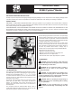
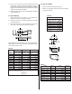
Figure 1. B2000 Cyclone
®
Bender
1.0 DESCRIPTION
The Cyclone
®
, GB model B2000 production bender is used to
bend EMT, IMC, rigid steel or rigid aluminum conduit. A single
bending shoe accommodates sizes
1
⁄ 2",
3
⁄ 4", 1", 1
1
⁄ 4", 1
1
⁄ 2" and
2" conduit. The shoe is driven by a 115 V, 15 A motor. The roller
housing consists of a single urethane roller support arm, and
three sets of nylon rollers.
The bender control pendant consists of a zero light, a green
power light, a jog push button, a push button for “Bend and
Return”. An 8' electrical cord connects the pendant to the
bender frame. The bender can be used in a horizontal or
vertical position.
The end plate contains an ON-OFF switch which is also a
circuit breaker. When the switch is turned on, the two leds will
flash red, then green to indicate normal function.
To avoid damaging the bender control circuit, an input voltage
sensing system is built into the control circuit. If input voltage
is less than 92 VAC or higher than 132 VAC the bender will
shut off. One of the two LEDS located on the end plate will light
to indicate whether high or low voltage exists.
Re-set the bender by turning unit off then on again. If the
incoming current voltage has not been corrected, the bender
will not operate. The voltage range must be within 92 VAC to
132 VAC. Any situation which causes a voltage drop or
increase must be corrected before using the B2000 Bender.
Voltage drops may be caused by:
• Extension cords that are too long.
• Extension cords made of light (16-18 gauge) wire.
• Multiple power tools on a single circuit.
• Other devices which require high amperes to operate.
2.0 WARNINGS
CAUTION: During pipe bending, stand behind the
frame handle. Keep hands, clothing and control cord away
from the bending shoe and rollers.
WARNING: Do not operate the bender on damp or
wet surfaces. Do not stand on wet surfaces while
operating the bender.
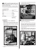
CAUTION: To prevent damage to the bending shoe,
do not allow the clamping jaws to strike the upper roller
support arm when the shoe is rotating. Position the roller
housing against the frame stop. See Figure 1.
CAUTION: Select an operating area large enough to
permit loading pipe section and bending without striking
objects or personnel.
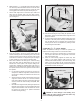
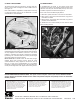
WARNING: To avoid possible injury, do not place
fingers under the bottom edge of the bending shoe. See
Figure 2.
Bending Shoe
Pendant
Control
High/Low
Voltage
Indicator
Frame Stop
Upper
Roller