
operation manual


GB
- 23 -
•
Original operating instructions
•
Safety instructions
3. Proper use
The chain is designed exclusively for sawing
wood. You may only fell trees if you have received
the appropriate training. The manufacturer cannot
be held liable for damage caused by improper or
incorrect usage.
The equipment is to be used only for its prescri-
bed purpose. Any other use is deemed to be a
case of misuse. The user / operator and not the
manufacturer will be liable for any damage or inju-
ries of any kind caused as a result of this.
Please note that our equipment has not been de-
signed for use in commercial, trade or industrial
applications. Our warranty will be voided if the
machine is used in commercial, trade or industrial
businesses or for equivalent purposes.
4. Technical data
Engine displacement ............................... 41 cm
3
Maximum engine capacity ....................... 1.5 kW
Bar length ...............................................33.5 cm
Cutter rail length ................................ 14” (35 cm)
Chain pitch ................................ (3/8”), 9.525 mm
Chain thickness ........................(0.05”), 1.27 mm
Idling speed ............................... 3300 ± 300 rpm
Maximum speed with
cutting equipment .............................. 11000 rpm
Tank capacity ............................................260 ml
Oil tank capacity ........................................210 ml
Anti-vibration function ....................................Yes
Chain wheel teeth ................. 6 teeth x 9.525 mm
Chain brake ....................................................Yes
Clutch ............................................................Yes
Automatic chain lubrication ............................Yes
Low-kickback chain ........................................Yes
Net weight without chain and chain bar ......4.5 kg
Net weight (dry) .........................................5.4 kg
Fuel consumption (specifi c) ............. 702 g / kWh
L
pA
sound pressure level ........................ 99 dB(A)
K
pA
uncertainty ........................................ 3 dB(A)
L
WA
sound power level .......................... 114 dB(A)
K
WA
uncertainty ..................................... 1.5 dB(A)
Vibration a
hv
(front handle) ..............max. 6.5 m/s
2
K
hv
uncertainty .........................................1.5 m/s
2
Vibration a
hv
(rear handle) ..............max. 6.0 m/s
2
Khv uncertainty .......................................1.5 m/s
2
Chain type .........................OREGON 91P053X
Bar type .........................OREGON 140SDEA041
Spark plug .................................................L8RTF
5. Before starting the equipment
Danger: Do not start the engine until the saw is
fully assembled.
Caution: Wear protective gloves at all times when
handling the chain.
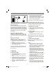
5.1 Fit the chain bar
To ensure that the bar and the chain are supplied
with oil, USE ONLY THE ORIGINAL BAR. The oi-
ling hole (Fig. 2/Item A) must be kept clear of dirt
and any build-up of residue.
1. Make sure the Chain brake lever is pulled
back into the DISENGAGED position (Fig.
3A)
2. Remove the bar fastening nut (B). Remove
the cover (Fig. 3B).
3. Run the adjustment screw (D) COUNTER-
CLOCKWISE until the TANG (E) (projecting
prong) is to the end of its travel toward the
clutch drum and sprocket (Fig. 3B/3C).
4. Fit the open end of the chain bar over the die
bar pins (F) (Fig. 3C/3D).
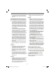
5.2 To install saw chain
1. Spread chain out in a loop with cutting edges
(A) pointing CLOCKWISE around loop (Fig.
4A).
2. Slip the chain around the sprocket (B) behind
the clutch (C). Make sure the links fi t between
the sprocket teeth (Fig. 4B).
3. Guide the drive links into the groove (D) and
around the end of the bar (Fig. 4B).
NOTE: The saw chain may droop slightly on the
lower part of bar. This is normal.
4. Pull the chain bar forward until the chain is
closely seated. Make sure that all the drive
links are in the groove of the bar.
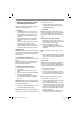
5. Attach the coupling cover (Fig. 5) and turn the
fastening nut (B) clockwise to secure it. The
chain is not allowed to slip off the guide bar
when you do this. Tighten the fastening nut by
Anl_GMSE_1535_SPK7_Teil1.indb 23Anl_GMSE_1535_SPK7_Teil1.indb 23 09.05.14 08:2909.05.14 08:29