
Hardware Manual

Mounting Instructions for
Model 75005 Side Slide and Model 75008
Side Slide with Mounting Hardware
Form 12.118
ASSEMBLY INFORMATION
1. Check parts against parts list.
2. Read Instructions completely before mounting.
3. NOTE: This product uses locknuts for a secure assembly.
Locknuts thread on harder than conventional nuts and
require a screwdriver and wrench for attachment.
TOOLS REQUIRED
1. Screwdriver
2. Crescent wrench adjustable to 7/16”
3. Drill
MOUNTING GUIDELINES
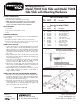
For best utilization of your helmsman seat, it is recommended that the
seat be mounted:
a) As high as possible to enable a clear view over the bow.
b) As close as possible to the wheel, leaving just enough room to
slide on to the seat from the side (see fig. 1).
MODEL 75005 SIDE SLIDE
1. Position slide (A) on port or starboard bulkhead of boat so it will
allow seat to conform to the Mounting Guidelines given above.
When positioning, it is recommended that the mounting plate be
locked as far forward as possible. This will allow one to utilize
the full slide travel by attaching the seat close to the wheel (see
figs. 1 & 2).
2. Make certain that the slide is parallel to the deck surface and
that it will be no higher above the deck than the stanchion leg’s
measured length (see fig. 1 ).
3. Mount slide to side bulkhead using all 8 holes provided and
secure in position with fasteners that are suitable for boat’s
particular construction. NOTE: fasteners not provided.
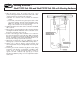
4. Attach seat to mounting plate with appropriate hardware and
fasteners (not provided). NOTE: Fig 2 shows an application of
seat mounting hardware model 75055, available.
5. Attach stanchion leg (not provided) to seat bottom for proper
support. NOTE: Stanchion leg included in model 75055 or
singly as 75014, available.
MODEL 75008 SIDE SLIDE WITH MOUNTING HARDWARE
1. Attach the 2 U-mounting brackets (B) to the mounting plate of the
slide (A) by aligning the holes in both and inserting bolts (C)
through the U-brackets, mounting plate and lockwashers (D).
Secure in position with nuts (E). See fig. 2.
2. Attach both support brackets (F) to U-mounting brackets (B) by
positioning brackets as in fig. 2, aligning their holes and
inserting bolts (G). Secure with locknuts (H). Finger tighten only.
These nuts will have to be removed in step 5.
please turn to other side
FIG. 1
FIG. 2
Write for
a Complete
Catalog
Phone: 651-459-9795
PO Box 8, 644 2nd Street E-mail: mail@garelick.com
St. Paul Park, Minnesota 55071 On the Web: www.garelick.com
4/04
Parts List for Model 75005
Ref. Factory No.
Letter Part No. Req. Description
A 59.500 1 Side Slide
Parts List for Model 75005
Ref. Factory No.
Letter Part No. Req. Description
A 59.500 1 Side Slide
B 50.109 2 U-mounting bracket
C 03.107 4 10 - 24 x 5/8" bolt
D 03.120 4 #10 lockwasher
E 03.025 4 10 - 24 x 5/8" bolt
F 59.026 2 Support Bracket
G 03.080 2 1/4 - 20 x 1-1/2" bolt
H 03.017 2 1/4 - 20 locknut
I 03.096 14 #10 x 7/8" screw
J 59.027 1 Socket casting
K 59.217 1 Stanchion leg 30"
L 10.001 1 1" White poly tip