
INSTALLATION AND OPERATION MANUAL Production Griddle CG-48F, CG-60F, CG-72F

Part # 4520498 (01/08) Page 5
NOTE: The griddle plate may not rest
evenly on the unit body if the unit is
not properly leveled.
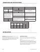
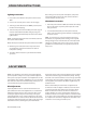
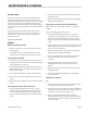
5. Each caster has a threaded stem
to aid in leveling only. No caster
should be adjusted beyond
a maximum of one-half inch,
(1/2”/13mm) of exposed thread
with the locking nut tight against
the stand leg, as shown.
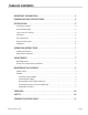
Clearances
This unit must be installed in accordance with the following
clearances in order to provide proper operation and
servicing of the appliance.
Clearances
Sides
Back
Left Right
Combustible
6”
(152mm)
6”
(152mm)
6”
(152mm)
Noncombustible 0” 0” 0”
Service Not Required
Type of Floor or Base Combustible
Gas Connections
1. A readily accessible gas shut-o valve is provided on each
unit, attached to the main manifold under the unit. The
gas supply connection must be made with minimum
3/4 inch NPT pipe. Larger than 3/4 inch (19 mm) supply
pipe may be required when a long run of supply pipe
is necessary. Consult the pipe capacity tables in the
installation code.
2. Have a qualied gas technician check the gas pressure
to make certain that the existing gas facilities (meter,
piping, etc.), will deliver the BTU’s of gas required at the
unit, with no more than 1/2 inch (12 mm) water pressure
drop. When checking pressure, be certain that all the
equipment on the same gas line is turned “ON”.
3. The appliance and its individual shut o valve must be
disconnected from the gas supply piping system during
any pressure testing of that system at test pressures in
excess of 1/2 PSIG. (3.45 KPA).
We suggest installation, maintenance and repairs should be
performed by your local authorized service agency listed in
your information manual pamphlet.
In the event you have any questions concerning the
installation, use, care or service of the product, write or call
our Product Service Department.
This product must be installed by professional personnel as
specied. Garland/U.S. Range products are not approved or
authorized for home or residential use, but are intended for
commercial applications only. Garland / U.S. Range will not
provide service, warranty, maintenance or support of any
kind other than for commercial applications.
General Information
Damage Check: check carton or crate for possible damage
incurred in shipping. After carefully examining, check for
“concealed” damage. Report any damage immediately to
your carrier.
Legs, Casters & Leveling
1. The unit must be installed on the legs or casters
provided. A minimum 4 inch (101 mm) air space must
be maintained below the unit for required air ow to the
burner systems. Avoid placing any objects under the unit
which could obstruct air ow to the burner systems.
2. For models equipped with casters,the installation shall be
made with a connector that complies with the Standard
for Connectors for Moveable Gas Appliances, ANSI
Z21.69/CSA 6.16, Addenda Z21.69B-2006/CSA 6.16B-2006
(or latest edition), and a quick-disconnect device that
complies with the Standard for Quick Disconnects for Use
with Gas Fuel, ANSI Z21.41/CSA 6.9, Addenda Z21.41A-
2005/CSA 6.16A-2005 (or latest edition).
3. Adequate means must be provided to limit movement of
the appliance without depending on the connector and
quick disconnect device or associated piping. This can
be accomplished by attaching restraining chains/cables
from oor or rear wall to rear of unit.
Ensure front casters are kept in the locked position except
when the unit must be moved for cleaning or servicing,
etc.
4. When the unit is installed in its operating location, level
the unit by adjusting the leveling legs. Use a level across
the front rear, and sides of each unit.
1/2"
(13mm)
MAX
1/2"
(13mm)
MAX
INSTALLATION Continued