SERVICE MANUAL INDUCTION COOKERS WITH RTCS TECHNOLOGY (REAL TIME TEMPERATURE CONTROL SYSTEM COUNTER TOP/BUILT IN/WOK MODELS NITATION SA C LIS T E D CM 86037 IMPORTANT NOTE: INDUCTION COOKERS MANUFACTURED WITH RTCS TECHNOLOGY WILL HAVE FIVE DIGITS IN THE CENTER OF THE SERIAL NUMBER: EXAMPLE: BA06.00001.0505 MODELS GIU 1.5 (BH/BA 1500) GIU 1.8 (BH/BA 1800) GIU 2.5 (BH/BA 2500) GIU 3.5 (SH/BA 3500) GIU 5.0 (SH/BA 5000) GIU 2.5 BI (BH/IN 2500) GIU 3.5 BI (SH/IN 3500) GIU 5.0 BI (SH/IN 5000) GIWOK 3.
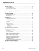
TABLE OF CONTENTS SECTION 1 –SAFETY . . . . . . . . . . . . . . . . . . . . . . . . . . . . . . . . . . . . . . . . . . . . . . . . . . . . . . . . . . . . 3 Description Of Warning Signs . . . . . . . . . . . . . . . . . . . . . . . . . . . . . . . . . . . . . . . . . . . . . . . . . . . . . . . . . . . . . . . . . . . . 3 Personnel Qualification And Training. . . . . . . . . . . . . . . . . . . . . . . . . . . . . . . . . . . . . . . . . . . . . . . . . . . . . . . . . . . . .
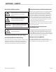
SECTION 1 –SAFETY Description Of Warning Signs Identifies safety information about dangers which may cause serious personal injury if equipment is not operated properly. Dangerous voltage warning symbol, indicates a risk of electric shock and hazards from dangerous voltage. CAUTION Indicates a hazard or unsafe practice which could result in minor personal injury or property damage. Electromagnetic field.
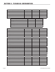
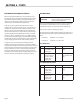
SECTION 2 – TECHNICAL INFORMATION Model BH/BA (Counter models) 120 V/1 Ph 208 V/1 Ph 240 V/1 Ph Wattage kW 1.5/1.8 kW 2.5/3.5 kW 2.5/3.5 kW 12.5/15 12/14.5/17 10/12.5/14.5 Power factor Cos ϕ >0.95 >0.95 >0.95 Discharge rate mA 4 4 4 190 (7.5”) 190 (7.5”) 190 (7.5”) Current A ∅ Coil mm Model BH/IN (Counter Models) 208 V/1 Ph 240 V/1 Ph 2.5 kW 2.5 kW 12 10 Power factor Cos ϕ >0.95 >0.95 Discharge rate mA 4 4 190 (7.5”) 190 (7.
Maximum tolerance of power supply Nominal voltage +6/-10 % Frequency 50/60 Hz Protection class IP X0 Min. diameter of pans Approx. 12 cm ( 4.7” ) Max. ambient temperature: stockage -20°C to 70°C (-4°F to 158°F) Max. ambient temperature: function -5 °C to 40°C (23°F to 104 °F) Max. relative humidity of air: stockage 10 to 90 % Max.
SECTION 4 – TESTS Pan Material For Induction Cookers When cooking with induction it is very important to use the appropriate pan material. The bottom of the pan is the element that closes the magnetic field generated by the induction coil. We highly recommend only appropriate induction pans be used with this equipment. A quick test can be performed to determine if a pan is appropriate. For this test you will need 1- Liter (34 ounces) of water at a temperature of 20°C (68°F).
Power Rating Test Of The Components The heating area is warmed up by the hot pan. To avoid injuries (burns) do not touch the heating area. ATTENTION Step Action Level Result 1 Place the pan on the heating area until water is boiling 9 (12) Heat, water is boiling 2 Reduce the power by turning slowly the control knob (12) 9...1 The power cord must be disconnected from the power supply.
Transistor module (IGBT) G CU (RTCS) Sensors E C The IGBT (Insulated Gate Bipolar Transistor) is fixed onto the power print (board) with three solder connections. The IGBT Transistor has as a supplementary protection an integrated recovery diode. To begin, measure the on-state voltage of this diode. The forward voltage of this diode is approximately 0.5VDC. If the recovery diode shows a short circuit or an interruption, the IGBT transistor is defective and must be replaced.
Measurements taken across points shown. SECTION 5 – MAINTENANCE/SERVICE Maintenance work must only be completed by authorized personnel. Before beginning any maintenance work, ensure that all power supply is disconnected and the appliance has had an opportunity, to cool down. It is important that the following maintenance procedures be performed as recommended. Such preventative maintenance measures will extend the life of this equipment and will provide trouble free operation.
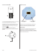
General Checks • Protection connection grounded? • Screwed connections all tight? • Isolations of cables? • Any kind of liquids that have entered the cooker? • Dirt in the cooker? Figure # 1 - Correct Coil (Spoil) Connection This connection must be well insulated and slightly bent upwards so the terminal end, does not make contact with the high voltage section on the power board. Coil wires must be tightly twisted together and precisely placed.
Figure # 2 – Examples of Incorrect Coil (Spoil) Connections Coil wires not twisted tightly together or precisely placed. Coil terminals connected in the incorrect direction. Coil terminals connected in the incorrect direction. Coil terminals connected in the incorrect direction.
SECTION 6 – FAULT FINDING General Information Do not attempt to open the cooker when it is connected to the power supply. Dangerous high voltage components will be exposed! CAUTION The induction cooker may only be serviced by authorized service personnel. Should the (Ceran Glass) become broken or cracked, turn off the cooker immediately and disconnect the electrical power supply to the unit. Do not touch any parts inside the cooker. Before replacing a part, check the wiring.
Number Of Flashing Signals Error Code 8 -........-........-........ Significance (Asterisk Refers To Notes At End Of Chart) Sensor error*** Measures To Take a. Check Cu coil b. Check heat sink sensor c. Check RTCS-sensor d. Check board sensor 12 13 17 18 Power reduction, heat sink temperature ** Power reduction, temperature of cooking surface ** a. Turn the power level down b. Check fan a. Take pan off until cooking area has cooled down b.
Flow chart to fault finding Unit does not operate Check Power Supply Replace Fuse Short circuit connection Potentiometer? Check potentiometer connection No No Check if fuse is installed correctly and power supply Yes Connection OK? Check LED Defective Replace LED OK Yes OK Check power cord/plug & socket OK Disassemble Cooker top assembly Connect Unit Replace Power Board Defective DefectIve Contact Electrician Is there any LED Indication? No Yes Check fuse T10A Defective Check rectifie
SECTION 7 – EXCHANGE OF SPARE PARTS • Turn induction unit back in normal position. CAUTION All spare parts and or accessories, may only be replaced by authorized service personnel. • Lift cover, turn away at the right side, put it at the side panel. • Remove coil carrier: remove 2 stop nuts at the left. • Remove M4 screws. CAUTION In order to guarantee safety, use only genuine OEM spare parts and accessories purchased directly from a Garland authorized part/service distributor.
• Place short circuit service plug into the power print board across the (Poti-LED) as showed in the photo below. IMPORTANT NOTE: When replacing the power board and or induction coil with RTCS sensors, you must reset all parameters. IMPERATIVE! Pay close attention to whether you receive a feedback signal from the PC or Laptop after every change. This will be your signal that the change has been accepted successfully.
4. Not valid for WOK cookers. The parameters on the CPU can now be changed! The unit temperature and the ambient temperature must amount to 25°C (+/- 4°C) or 77°F (+/- 39°F). Press the key [ ; ]. On the console appears the message “please confirm”. Press the key [ ; ] again. The CU (RTCS) sensor will now be initialized on 25°C (77°F). The following message now appears on the monitor: save CU sensor : 25°C 5. Set the limit of the (mains) power current.
Parameters For (Mains) Power Current And Pan Detector Page 18 Item Number (Article No.) 99560101 99560102 99560103 99560104 99560105 99560106 99560107 99560108 99560109 99560110 99560111 99560112 BH/BA 1500, 120VAC, 1N, 1,5kW (GIU 1.5) BH/BA 1800, 120VAC, 1N, 1,8kW (GIU 1.8) BH/BA 2500, 208VAC, 1N, 2,5kW (GIU 2.5) BH/BA 2500, 230VAC, 1N, 2,5kW (GIU 2.5) BH/BA 2500, 240VAC, 1N, 2,5kW (GIU 2.5) BH/BA 3000, 208VAC, 1N, 3kW (GIU 3.0) BH/BA 3000, 230VAC, 1N, 3kW (GIU 3.0) BH/BA 3000, 240VAC, 1N, 3kW (GIU 3.
SECTION 9 – IR (INFRARED) INTERFACE To begin the IR communication, you will need the HyperTerminal software which is available in Microsoft Windows under, Start =>Program=>Accessories => HyperTerminal. Prior to the first use, HyperTerminal should be configured properly. Garland service requires the following settings listed below: 2400bps, 8bit, no parity, 1 stop bit, hardware protocol. First connect the IR adapter into your PC or laptop computer.
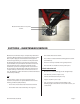
Select the following settings: 2400 Bits/sec., 8 Databits, no parity, 1 Stop bit, Hardware protocol. Setting IR 2400.ht should be saved so that there will be no need to put them again and the connection can be built-up by selecting symbol IR2400.ht. Figure # 3 – IR Adapter position for counter top (base-line) cookers For all counter top induction cookers (excluding all WOK models), position the IR adapter tool to the lower left hand corner of the ceran glass as shown in photo.
Figure # 4 – IR Adapter position for built-in (install-line) cookers IR Adapter to be positioned directly over rectangular opening, shown in photo. IR Adapter tool in position. Place Wok Bowl top assembly back onto cooker as shown and, begin testing using IR adapter tool.
Page 22 PE L3 (230V L2) (208V L2) (240V L2) L2 L1 Main (Power) Filter DC Power Supply AC 12VAC 24VDC 5VDC -5VDC GND 5VDC AC TB Potentiometer 24VDC 24VDC DC Rectifier LED 12VAC DC CPU -5VDC 24VDC IR Adapter AC IGBT - Transistor Fan T KK T Cu1 T CU2 Coil RTCS Sensors SECTION 10 – WIRING BLOCK SCHEMATIC Part # 4521635 (03/04/08)
Part # 4521635 (03/04/08) Page 23