
User guide


Page 10
INSTALLATION
1. The installation and connection must be performed by a
licensed gas technician in compliance with local codes,
or in the absence of local codes, with CAN/CGA-B149
Installation Code or with the national Fuel Gas Code, ANSI
Z223.1/NFPA No. 54 – Latest Edition.
2. The correct type of gas for which the unit was
manufactured is noted on the rating plate, and this type
of gas must be used.
3. If it is a new installation have the gas authorities check
meter size and piping to assure that the appliance is
supplied with necessary amount of gas pressure required
to operate properly.
4. The gas pressure must be checked when the appliance
is installed, to ensure that the gas pressure is the same
as speci ed on the rating plate. If necessary, pressure
adjustments can be made at the pressure regulator,
supplied on each unit.
NOTE: When installing as a ush mount pressure regulator
connection, (to allow for equipment installations against
a non-combustible wall), a certi ed exible gas hose and
quick disconnect assembly is required to allow the unit to
be moved in the event an adjustment of the gas pressure
regulator is required.
5. Have a quali ed gas technician check the gas pressure
to make certain that existing gas facilities (meter, piping,
etc.) will deliver the BTU’s of gas required at the appliance
with no more than ½” water column pressure drop. When
checking pressure, be certain that all the equipment on
same gas line is turned to the “ON” position.
6. The appliance and its individual shut o valve must be
disconnected from the gas supply piping system during
any pressure testing of that system at test pressures in
excess of 1/2 PSIG. (3.45 KPA).
7. The appliance must be isolated from the gas supply
piping system by closing its individual manual shut o
valve during any pressure testing of the gas supply piping
system at test pressures equal to or less than 1/2 PSIG.
(3.45 KPA).
8. Make certain that the new piping, joints and connections
have been made in a clean manner and have been
purged, so that the piping compound, chips, etc., will not
clog pilots, valves and/or controls. Use pipe joint sealant
that is certi ed for use with lique ed petroleum gas.
9. WARNING: Check gas connections for leaks, using soap
solution or similar means.
Do Not Check with an Open Flame.
Leg Installation
Your new appliance has been supplied with 4”(102mm)
adjustable legs. These legs are threaded into holes on the
bottom. Once the legs are installed turn the leveling foot at
the bottom of the leg.
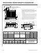
UNDERSIDE OF UNIT
4" [102mm]
ADJUSTABLE LEG
LEG INSTALLATION
LEVELING FOOT
Level the appliance by adjustment of leveling bolts or legs.
Use a spirit level and check for level four ways; across front
and back, then down left and right edges. Level any adjacent
units to the rst. A griddle may not rest evenly on the
appliance body if it is not properly leveled.
Part # 4531237 Rev 2 (09/09/13)