SERVICE MANUAL JACK IN THE BOX GAS XPRESS GRILLS, MODELS XG24-JIB, XG36-JIB FOR YOUR SAFETY: DO NOT STORE OR USE GASOLINE OR OTHER FLAMMABLE VAPORS OR LIQUIDS IN THE VICINITY OF THIS OR ANY OTHER APPLIANCE WARNING: IMPROPER INSTALLATION, ADJUSTMENT, ALTERATION, SERVICE OR MAINTENANCE CAN CAUSE PROPERTY DAMAGE, INJURY, OR DEATH.
TABLE OF CONTENTS DIMENSIONS AND SPECIFICATIONS, XG24-JIB MODEL . . . . . . . . . . . . . . . . . . . . . . . . . . . . . . 4 DIMENSIONS AND SPECIFICATIONS, ++XG36-JIB MODEL . . . . . . . . . . . . . . . . . . . . . . . . . . . 5 Plug Configuration . . . . . . . . . . . . . . . . . . . . . . . . . . . . . . . . . . . . . 6 INTRODUCTION . . . . . . . . . . . . . . . . . . . . . . . . . . . . . . . 7 Warranty . . . . . . .
TABLE OF CONTENTS continued CALIBRATION . . . . . . . . . . . . . . . . . . . . . . . . . . . . . . . 33 Bi-Weekly Calibration: . . . . . . . . . . . . . . . . . . . . . . . . . . . . . . . . 33 Probe Locations: . . . . . . . . . . . . . . . . . . . . . . . . . . . . . . . . . . . . . . 34 TROUBLESHOOTING . . . . . . . . . . . . . . . . . . . . . . . . . 35 ERROR MESSAGES: PROBE ERROR: . . . . . . . . . . . . . . . . . . . . . . . . . . . . . . . . .
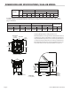
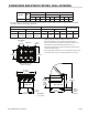
DIMENSIONS AND SPECIFICATIONS, XG24-JIB MODEL Model Total kW Load XG24-JIB 8.66 Loading kW Per Phase Nominal Amps Per Line 208/240V 3ph 208V 3-Phase Delta 240V 3-Phase Delta X-Y X-Z Y-Z 2.66 3.33 2.66 X Y Z X Y Z 24.90 22.14 24.90 21.61 19.19 21.61 6’ (1.83m) electric cord and plug included in supplied accessory kit: 240V models are supplied with a #4-10AWG cord with a NEMA 5-30P plug, kit # 4525509. 208V models are supplied with a #4-6AWG cord with a NEMA 15-50P plug, kit # 4524785.
DIMENSIONS AND SPECIFICATIONS, XG36-JIB MODEL Nominal Amps Per Line Total Loading kW Per Phase kW 208/240V 3ph 208V 3-Phase Delta 240V 3-Phase Delta Load X-Y X-Z Y-Z X Y Z X Y Z Model XG36-JIB 12.99 4.00 4.99 4.00 37.43 33.30 37.43 32.43 28.90 32.43 6’(1.
SPECIFICATIONS continued Plug Configuration The grill is supplied with an electrical power supply cord and plug to match the specific voltage as it was constructed. The following table shows the correct plug configuration to match the model and voltage. Xpress Grill Cord and Plug Configuration P/N (includes electrical and gas inlet plumbing) Plug Type Cord Gauge Supplied NEMA Plug Y X GND 4524785 4-6AWG Model Voltage (3ph Delta) Maximum Current (Amps) Minimum Cord Gauge XG24-JIB 208 24.
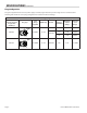
INTRODUCTION The Garland Xpress grill, for Jack in the Box provides a method for efficient two-sided cooking, while accommodating a variety of products. The unit will also serve as a flat grill, and meets all of Jack in the Box’s standards for safety, efficiency, and cleanliness. Warranty This warranty covers defects in material and workmanship under normal use providing that: a) The equipment has not been accidentally or intentionally damaged, altered or misused.
SAFETY continued When two sided cooking, the area between the upper platen and the griddle plate should be regarded as a “danger zone.” During two sided cooking the operator must not be within this danger zone. When used as a flat grill, then this area is no longer a danger zone, the platens do not move. WARNING: After turning the master power switch to the START position, the grill will go through initialization.
UNIT INSTALLATION Rating Plate Location IMPORTANT: Rating plates for this appliance are located in two places: 1) inside back panel on left side, 2) under front control panel on center. General Information This equipment must be installed by a competent factory trained, certified, licensed and / or authorized service or installation person. WARNING: This appliance must be properly grounded.
UNIT INSTALLATION continued The grill must be disconnected from the gas supply system when pressure testing of that system at pressures in excess of 1/2 psi (3.45kPa). Check the data plate to determine the proper type of gas before connecting the quick disconnect or piping from the building gas supply. An incoming gas pressure test nipple is provided on the incoming gas manifold for pressure checks.
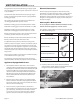
UNIT INSTALLATION continued B. Install the nipple assembly into the elbow (3/4” NPT) Refer to Photo A C. Install the manifold support bracket over the nipple attaching it to the circular bracket on the nipple. Do not tighten screws. Refer to Photo B Installation of Cord And Plug With Strain Relief: 1. Remove the left grease bucket support attached by two metal screws and the stainless steel left side body panel attached by five metal screws. 2.
UNIT INSTALLATION continued 4. Insert loose wires and strain relief cord end through the hole at the bottom of the unit. Refer to photo F and secure with locknut. Refer to photo E. Note: see diagram below for connections to terminal block. Wire leads from Cord and Plug Main Terminal Block of Grill Green-Ground G White - Z Z Black - Y Y Red - X X Photo F Grease Bucket: 5. Attached wire ends to terminal block as shown in next section and referenced in wiring diagrams at back of this manual.
UNIT INSTALLATION continued The gas valve, enrichment tube igniter and orifice must be changed to that supplied by the Authorized Service Agency for the gas you are changing to. On completion of changing these three components, you should test all joints for leaks, verify that the manifold pressure is adjusted to the value given in the specification pages in this manual, and repeat the burner air adjustment procedure. This is to be found on the following page in this manual.
GRILL CONTROLS WHEN PUSHED SIMULTANEOUSLY: "START COOK TIME COUNTDOWN" (flat grill cooking) OR "LOWER PLATEN" (two-sided cooking) LED INDICATORS DISPLAY CANCEL/ RAISE PLATEN BUTTON PRODUCT BUTTONS ON OFF MASTER POWER SWITCH POWER BUTTON PROGRAM BUTTON TEMPERATURE BUTTON ENTER BUTTON DOWN ARROW BUTTON UP ARROW BUTTON Master Power Switch: Display: Controls power to the grill and must be turned “ON” to start operation. The controller display will be active when the switch is “ON”.
GRILL CONTROLS continued Program Button: Enter Button: The primary function is to access Programming and Calibration of the grill. Push and hold for five (5) seconds. Display will ask for the code. After entering code, five programming features will be accessible “MENU ITEMS,” “SYSTEM INFO,”“SYSTEM SETUP,”“SERVICE MODE,” and “PRODUCT NAME LIB.” Function is to accept programming steps.
PLATEN ZEROING Turn Master power switch “ON”, wait for controllers to display “OFF”. Note: Release sheets should not be installed during this procedure. 1. Press and hold displayed. for three, (3) seconds. “ENTER CODE” is 2. Using the Product buttons, 0-9 enter the code, (1251). “ENTER CODE **** ” is displayed. 3. Press to enter the Programming Mode. “PROGRAMMING MODE MENU ITEMS” is displayed. 4. Press two, (2) times in succession to display “PROGRAMMING MODE SYSTEM SETUP.” 5. Press six, (6) times.
PLATEN ZEROING continued Platen Gapping Tool (PN 1838701) r we t Lo on Fr Left Ra Ba ise Rig ck ht “No-Go” “Go” Platen leveling should be done from one corner to the opposite corner. The adjuster nuts should be turned opposite of one another.
OPTIONAL ACCESSORIES Teflon Sheet - 1799302 Teflon Clip - 1851303 Grill Squeegee - 1868201 Teflon Tool - 4525560 Page 18 Part # JIBSM08 Rev 7 (08/04/09)
RELEASE MATERIAL INSTALLATION The following procedures are the procedures for installing the Teflon sheets on to the upper platen on the Garland Xpress grill. The components shown below are included with your grill when purchased. Slide release material rod through hemmed end of the release material sheet. Holding the bottom of the release material sheet in place, gently pull the sheet toward the front of the platen.
NORMAL OPERATION Installing Release Material: For installation instructions, see section on RELEASE MATERIAL INSTALLATION. A release material sheet must be replaced when: • Product sticks to release material. • Carbon build-up ruins taste or appearance. • Tearing occurs in the sheet’s cooking area. • Release material coating is worn off sheet. Lighting Instructions: 1. Ensure that the flexible gas hose is connected to the grill and the power cord is plugged into the receptacles. 2.
NORMAL OPERATION continued 4 To cancel a cook cycle at anytime the press the green CANCEL/RAISE PLATEN BUTTON . 5. During a cook cycle, the display shows the product recipe name in the first line and the remaining cook time count down in the second line. 6. The display shows the “SEAR” or “FLIP” alarm message with flashing in the second line if the current cooking product is flat recipe and the sear time or flip time is not zero. 7. A cook alarm sounds with a repeating beep pattern.
NORMAL OPERATION continued EXTENDED TIME: START DELAY: This option will add 6, 4 and 2 seconds to the time of the next three cooks respectively if the grill has had no activity for 5 minutes. Provided the temperature is not 25°F above set temperature for either the grill or the platen. This number is how long the operator must hold the GREEN (‘CANCEL/RAISE’) and BLACK buttons to start a cooking cycle for 2-sided recipes only.
CLEANING AND MAINTENANCE continued 9. Open one packet of high-temperature grill cleaner, (several cleaners may be available on the market), and empty the contents into a suitable container. (One packet will clean one grill.) 10. Firmly attach a no-scratch pad to a pad holder. 11. Dip the no-scratch pad into the grill cleaner, and spread a light coating of grill cleaner over the entire platen surface, back, front, and side edges of both upper platens. DO NOT SCRUB.
PROGRAMMING Programming Modes/Menu Sequence: System Information System Information Page 24 26 26 26 26 26 26 26 26 26 26 27 27 27 27 27 27 27 27 27 27 28 28 28 28 28 28 Part # JIBSM08 Rev 7 (08/04/09)
PROGRAMMING continued System Set-up System Set-up Part # JIBSM08 Rev.
PROGRAMMING continued Menu Items... 5. Use To Change the Cook Time of a Product: 1. Press and hold displayed. for three, (3) seconds. “ENTER CODE” is 2. Using the Product buttons, 0-9 enter the code, (1251). “ENTER CODE **** ” is displayed. 3. Press to enter Programming Mode. “PROGRAMMING MODE MENU ITEMS” is displayed. 4. Press 5. Use 6. Press 7. Use . “MENU ITEMS STANDBY” is displayed. and to choose the desired Menu Item. to display “(MENU ITEM) COOK TIME XX:XX” and to adjust the cook time.
PROGRAMMING continued To Change Product Button, “Key” Assignment 1. Press and hold displayed. for three, (3) seconds. “ENTER CODE” is 2. Using the Product buttons, 0-9 enter the code, (1251). “ENTER CODE **** ” is displayed. 3. Press to enter the Programming Mode. “PROGRAMMING MODE MENU ITEMS” is displayed. 4. Press 5. Use . “MENU ITEMS STANDBY” is displayed. and to choose the desired Menu Item. 6. Press six, (6) times to display “ASSIGN TO KEY (0-9 or NONE)”. 7.
PROGRAMMING continued To View the Flash Number: 1. Press and hold displayed. for three, (3) seconds. “ENTER CODE” is 2. Using the Product buttons, 0-9 enter the code, (1251). “ENTER CODE **** ” is displayed. 3. Press to enter the Programming Mode. “PROGRAMMING MODE MENU ITEMS” is displayed. 4. Press one, (1) time to display “PROGRAMMING MODE SYSTEM INFO.” 5. Press four, (4), times to view the Flash Number. “FLASH NUMBER X…X” is displayed. (Flash number varies by grill). 5.
PROGRAMMING continued 8. Press to return to “PROGRAMMING MODE SYSTEM SETUP” 9. Press again to exit. To Change the Alarm Volume: 1. Press and hold displayed. for three, (3) seconds. “ENTER CODE” is 2. Using the Product buttons, 0-9 enter the code, (1251). “ENTER CODE **** ” is displayed. 3. Press to enter the Programming Mode. “PROGRAMMING MODE MENU ITEMS” is displayed. 4. Press two, (2) times. “PROGRAMMING MODE SYSTEM SETUP” is displayed. 5. Press three, (3), times.
PROGRAMMING continued • • • Temperature is currently falling from a detected peak of 360°F or higher. Temperature is falling and has fallen 2°F from a detected peak that is within the 350-360°F range. (i.e. calibration would be allowed at 355°F if the achieved peak temperature was 357°F) Temperature is rising through the 350-360°F range as a result of a heat on pulse of less than 30 seconds. To Change Platen Set: 1. Press and hold displayed. for three, (3) seconds. “ENTER CODE” is 2.
PROGRAMMING continued To Change the Grill Function: To Change the Alarm Mode: 1. Press and hold displayed. 1. Press and hold displayed. for three, (3) seconds. “ENTER CODE” is for three, (3) seconds. “ENTER CODE” is 2. Using the Product buttons, 0-9 enter the code, (1251). “ENTER CODE **** ” is displayed. 2. Using the Product buttons, 0-9 enter the code, (1251). “ENTER CODE **** ” is displayed. 3. Press to enter the Programming Mode. “PROGRAMMING MODE MENU ITEMS” is displayed. 3.
PROGRAMMING continued Service Mode 3. Press to enter the Programming Mode. “PROGRAMMING MODE MENU ITEMS” is displayed. 4. Press three, (3) times. “PROGRAMMING MODE PROD NAME LIB” is displayed. 5. Press . “PROD NAME LIB” is displayed. 6. Press . “PROD NAME LIB” will be displayed on the top line, with a flashing cursor on the bottom line. 7. Use and to change the character, (A-Z, 1-9, , and hyphen are available). Use and move the cursor position. to 8. Press to save the new product name.
CALIBRATION Bi-Weekly Calibration: Tools: Digital Pyrometer with Surface Probe Warning: PERSONAL INJURY FROM BURNS MAY RESULT WHEN COMING IN CONTACT WITH HOT COOKING SURFACES. NOTE: Calibration of grills is done with release material sheets installed. NOTE: CALIBRATION REQUIREMENTS The control software will beep to the user when it is appropriate to calibrate.
CALIBRATION continued Probe Locations: The grill’s thermocouple probes are located on each section of the lower grill plate in the center of the cooking zone as shown in the diagram below. Each upper platen has one thermocouple probe in the center. 11.5" 11.5" 5.75" 11.5" 5.75" 22.5" 5.75" 11.5" 5.75" 11.5" 5.75" 22.5" TOP PLATEN (2 PLACES) 11.25" TOP PLATEN (3 PLACES) 11.25" GRILL PLATE GRILL PLATE 24" 24" 12" 12" 6.09" 6.09" 6.09" 6.
TROUBLESHOOTING ERROR MESSAGES: COMM ERROR: NOTE: WE STRONGLY SUGGEST THAT ANY INSTALLATION, MAINTENANCE AND REPAIRS SHOULD BE PERFORMED BY YOUR LOCAL GARLAND AUTHORIZED SERVICE AGENCY. Press ...occurs when the probe is open or not connected. The control will turn the heat off. If the fault is in the platen the grill can still be used with recipes that do not call for the platen. If the grill probe circuit is open, the grill will not operate.
TECHNICAL TROUBLESHOOTING Master Power (ON / OFF) Switch turned ON - Power light or indicator is not lit Control power cord(s) unplugged YES Reconnect power supply, Check Ansul reset NO Line voltage not present YES Circuit breaker at service panel is “OFF” or tripped Reset circuit breaker NO Check for Line voltage at terminal block terminals (#1 & #6) and (#2 & #6) YES Replace power switch YES Remove platen cover and check high limit...
TECHNICAL TROUBLESHOOTING continued Controller Displays “Too Hot” Current product selected requires a lower operating temperature that the previous one selected. YES Allow grill to cool down to current set temperature of selected product YES Replace Solid State Relay NO Zone is continuously heating, and temperature is rising. NO Allow grill to cool down below the TOO HOT temperature (79 degrees above set point) Part # JIBSM08 Rev.
TECHNICAL TROUBLESHOOTING continued Controller Displays “FAULTY ELEMENT OR SHORTED PROBE” Only 1 or 2 zones LED lights are RED Replace Bad Contactor Check for 3-phase voltage at primary side of main contactors YES Check for 3-phase voltage at secondary side contactor NO YE S NO Check to ensure that 3-phase power cords are securely fastened and plugged into their receptacles YE S Check for disconnected or damaged molex plugs going to heating elements NO Ensure that main 3-phase circuite breakers ar
TECHNICAL TROUBLESHOOTING continued Controller displays “PROBE ERROR” Controller displays “Probe ERROR” when grill is turned on. Disconnect suspected thermocouple and check continuity. YES NO NO Controller displays “Probe ERROR” during normal operation. Has suspected zone overheated? YES YES NO Check all connections on thermoscouple interface board.
TECHNICAL TROUBLESHOOTING continued Controller Displays “HEATING ERROR or PROBE ERROR PLATEN and GRILL LED’s are RED (Both Sides) NO Check for 3-phase voltage at primary side of main contactors YES Check for 3-phase voltage at secondary side of contactor YES See Technical Troubleshooting “Controller display is BLANK, Main Power (ON/OFF) Light IS LIT” Check for disconnected molex plugs going to heating elements NO Check to ensure that 3-phase power cords are securely fastened and plugged into their re
TECHNICAL TROUBLESHOOTING continued Controller Display is BLANK, Main Power (ON / OFF) light or indicator is LIT Probable diagnosis Check for 120 VAC at terminal marked “LIM” & “N” Part # JIBSM08 Rev.6 (08/04/09) YES Check for loose or disconnected black wires on coil of contactor and black wires going to 24VAC transformers. YES Repair Open or damaged wire YES Check opposite side NO Trace circuit for terminal marked “LIM” brown wire to back of unit and into molex plug. Check for open circuit.
TECHNICAL TROUBLESHOOTING continued Master Power (ON / OFF) Switch turned ON - Power Light in On - Grill is not heating Controller display reads “OFF” YE S Press the MENU SELECT button.
TECHNICAL TROUBLESHOOTING continued Controller Displays “MOTOR OVER CURRENT” - Platen does not move at all Check voltage of limit switches. 5.6 VDC when switch is Open, 0 VDC when switches are closed. YES Replace defective Limit Switch NO Check for 120 volts at the motor speed controller. Pins 3 & 4. YES Check for 120 - 140 VDC on pins 1 & 2 or Motor Speed Controller. NO Replace defective Motor Speed Controller.
TECHNICAL TROUBLESHOOTING continued Controller Displays “IGNITION FAILURE” - No flame at all Do the burners light at all? Does the flame go out? YES Check for proper gas pressure - Incoming & manifold pressure YES NO NO Check quick disconnect for improper connection YES Reconnect quick disconnect on gas supply hose YES Adjust incoming & burner pressure for gas type NO Check for incoming gas pressure at the main incoming gas manifold Check for proper microamp reading YES Turn gas valve ON NO
TECHNICAL TROUBLESHOOTING continued Controller Displays “IGNITION FAILURE” - Module is sparking, flame comes on and goes out Dig Gas Valve Open? Check for 120 VAC across gas Valve, terminal 3&4 NO Check for 120VAC output from ignition module, terminal VALVE & VALVE. YES Check for 3.5” W.C. (NAT GAS), 10” W.C. (LP) burner pressure. NO YES NO NO YES Check gas view port to ensure flame is lighting.
LINEAR ACTUATOR REPLACEMENT 1. Disconnect the cable from the Motor Speed Control. 6. Push the pin through the actuator base toward the inside of the grill. Reach around to the inside and remove. 2. Disconnect the motor leads from the wire harness. 7. Remove the Linear Actuator from the grill, carefully pulling it out the rear. 3. With the platen in the UP position, support it with a pry bar, 2x4, etc., from behind the platen arm assembly. Pull the platen arm toward the rear of the grill to insert. 8.
LINEAR ACTUATOR REPLACEMENT continued 11. Gently fit clevis clip through top of actuator shaft and cross member bar. Use pry bar to align holes. 12. Reconnect wires as shown in the photos to the right. Part # JIBSM08 Rev.
Page 48 Part # JIBSM08 Rev 7 (08/04/09)
PARTS LIST PARTS LIST MASTER SERIES XG24-JIB XPRESS GRILL GAS Contents XPRESS - GRILL COMPLETE VIEW . . . . . . . . . . . . . . . . . . . . . . . . . . . . . . . . . . . . . . . . . . . . . . . . 50 XPRESS GRILL ACTUATOR . . . . . . . . . . . . . . . . . . . . . . . . . . . . . . . . . . . . . . . . . . . . . . . . . . . . . . . 52 XPRESS GRILL PLATEN . . . . . . . . . . . . . . . . . . .
XPRESS - GRILL COMPLETE VIEW MODEL XG24-JIB XG24-JIB#1 Page 50 Part # JIBSM08 Rev 7 (08/04/09)
GARLAND PARTS IDENTIFICATION Gas - Xpress Grill Complete Exploded View - Model: XG24-JIB ITEM PART # DESCRIPTION 1 4516708 Body Base Wa 2 4516718 Plate Wa 3 Page 52 Actuator Assembly 4 Page 54 Platen Assembly 5 Page 56 Burner Assembly 6 Page 58 Component Bracket Assembly 7 Page 60 Heat Sink Assembly 8a 4516978 Caster, Nonlocking 8b 4517563 Caster, Locking 9 4516689 Circuit Support 10a 4516980 Circuit Brkr, 1 Pole 10b 4517425 Circuit Brkr, 3 Pole 11 4516687 Circuit Box 12 4516688 Circuit Cover 13 4516685 Fro
XPRESS GRILL ACTUATOR ASSEMBLY VIEW MODEL XG24-JIB XG24-JIB#2 Page 52 Part # JIBSM08 Rev 7 (08/04/09)
GARLAND PARTS IDENTIFICATION Gas - Xpress Grill Actuator Assembly View - Model: XG24-JIB ITEM PART # DESCRIPTION 1 4516080 Actuator Frame Wa 2 4516096 Pillow Block 3 1812401 Actuator 4 1857601 Switch Bracket 5 1855601 Upper/Lower Platen Limit Switch 6 1858001 Actuator Mount Block 7 4516097 Actuator Base Bracket * NOT ILLUSTRATED RECOMMENDED STOCK PARTS Part # JIBSM08 Rev.
XPRESS GRILL PLATEN ASSEMBLY VIEW MODEL XG24-JIB Available Separately if needed Available as a complete assembly only Available Separately if needed XG24-JIB#3 Page 54 Part # JIBSM08 Rev 7 (08/04/09)
GARLAND PARTS IDENTIFICATION Gas - Xpress Grill Platen Assembly View - Model: XG24-JIB ITEM 1 2 3 4 5 6 7 8 9 10 11 12 13 14 15 16 17 18 19 20 PART # DESCRIPTION 4516085 Platen Arm 4516087 Carriage Block, Rt 4516088 Carriage Block, Lt 1858501 Pivot Stop Knob 1858502 Pivot Stop Pin 4516092 Platen Lid 4517021 3/8 Connector, 45 Deg 4517022 Platen Conduit 4517020 3/8 Connector, 90 Deg 4517008 Teflon Bar, Rear 4516094 Teflon Holder, Rear (Not Available Separately) 4516091 Platen Cowl (Not Available Separately)
XPRESS GRILL BURNER ASSEMBLY VIEW MODEL XG24-JIB XG24-JIB#4 Page 56 Part # JIBSM08 Rev 7 (08/04/09)
GARLAND PARTS IDENTIFICATION Gas - Xpress Grill Burner Assembly View - Model: XG24-JIB ITEM PART # DESCRIPTION 4517403 Burner Assembly, Lp 1 4517462 Burner Assembly, Nat 2 4517396 Flue Box, Inner 3 4517397 Flue Box, Outer 4 4517398 Flue Bottom 5 4517399 Flue Top 6 4517401 Flue Riser, Inner 7 4517400 Flue Riser, Outer 8 4524066 Igniter 9 4517967 Ignition Cable 10 1864701 Gas Valve - Nat * NOT ILLUSTRATED RECOMMENDED STOCK PARTS Part # JIBSM08 Rev.
XPRESS GRILL COMPONENT BRACKET ASSEMBLY VIEW MODEL XG24-JIB XG24-JIB#5 Page 58 Part # JIBSM08 Rev 7 (08/04/09)
GARLAND PARTS IDENTIFICATION Gas - Xpress Grill Component Bracket Assembly View - Model: XG24-JIB ITEM PART # DESCRIPTION 1 4516682 Component Bracket 2 4516989 Motor Speed Control 3 4516079 Contactor Bracket 4 1269800 24 Volt Transformer 5 1637001 Contactor 6 1864901 Ignition Module * NOT ILLUSTRATED RECOMMENDED STOCK PARTS Part # JIBSM08 Rev.
XPRESS GRILL HEAT SINK ASSEMBLY VIEW MODEL XG24-JIB XG24-JIB#6 Page 60 Part # JIBSM08 Rev 7 (08/04/09)
GARLAND PARTS IDENTIFICATION Gas - Xpress Grill Heat Sink Assembly View - Model: XG24-JIB ITEM PART # 1 4516116 2 4516988 3 4517392 * NOT ILLUSTRATED RECOMMENDED STOCK PARTS Part # JIBSM08 Rev.
REVISION HISTORY GARLAND PARTS IDENTIFICATION Revision History REV.
PARTS LIST continued PARTS LIST MASTER SERIES XG36-JIB XPRESS GRILL GAS Contents GRILL COMPLETE ASSEMBLY . . . . . . . . . . . . . . . . . . . . . . . . . . . . . . . . . . . . . . . . . . . . . . . . . . . . 64 ACTUATOR ASSEMBLY . . . . . . . . . . . . . . . . . . . . . . . . . . . . . . . . . . . . . . . . . . . . . . . . . . . . . . . . . . 68 PLATEN ASSEMBLY . . . . . . . . . . . . .
GRILL COMPLETE ASSEMBLY ASSEMBLY VIEW MODEL XG36-JIB XG36 - JIB#1 Page 64 Part # JIBSM08 Rev 7 (08/04/09)
GARLAND PARTS IDENTIFICATION Gas - Xpress Grill Complete Exploded View - Model: XG36-JIB ITEM 1 2 3 4 5 6 7 8A 8B 8C 9 10 11 12 13 14 15A PART # DESCRIPTION 4516058 Body Base Weld Assembly 4517657 Plate Weld Assembly Page 68 Actuator Assembly Page 70 Platen Assembly Page 72 Burner Assembly Page 74 Component Bracket Assembly Page 76 Heat Sink Assembly 4516978 Caster, Nonlocking 4517563 Caster, Locking 4520678 Caster Kit - Locking & Nonlocking 4516113 Circuit Support 4517814 Circuit Brkr, 3 Pole 4516111 Circ
GARLAND PARTS IDENTIFICATION Gas - Xpress Grill Complete Exploded View - Model: XG36-JIB ITEM PART # DESCRIPTION 39 Page 72 Flue Assembly 40 1869301 Transformer Bracket 41 4516114 Circuit Brace 42 4520578 Grill Plate Thermocouple 43 1866103 Strain Relief Wire 12.
Part # JIBSM08 Rev.
ACTUATOR ASSEMBLY ASSEMBLY VIEW MODEL XG36-JIB XG36-JIB#2 Page 68 Part # JIBSM08 Rev 7 (08/04/09)
GARLAND PARTS IDENTIFICATION GAS - XPRESS GRILL ACTUATOR ASSEMBLY VIEW - MODEL: XG36-JIB ITEM PART # DESCRIPTION 1 4516080 Actuator Frame Wa 2 4518156 Pillow Block Assembly 3 4525541 Linear Actuator 4 1857601 Switch Bracket 5 1855601 Upper/Lower Platen Limit Switch 6 4518787 Actuator Mount Block (Painted) 7 4516097 Actuator Base Bracket 8 8003424 1/4” – 20 X 2.250” Shoulder Bolts 9 8000306 1/4” Lock Washer * NOT ILLUSTRATED RECOMMENDED STOCK PARTS Part # JIBSM08 Rev.
PLATEN ASSEMBLY ASSEMBLY VIEW MODEL XG36-JIB Available Separately if needed Available Separately if needed Available as a complete assembly only Available Separately if needed Available Separately if needed Available Separately if needed XG36 - JIB#3 Page 70 Part # JIBSM08 Rev 7 (08/04/09)
GARLAND PARTS IDENTIFICATION Gas - Xpress Grill Platen Assembly View - Model: XG36-JIB ITEM 1 2 3 5 6 7 8 9 10 PART # 4516085 4520422 4520423 4522581 4516092 4517021 4517022 4517020 4517008 11 4516094 12 13 14 15 16 4516091 1859102 1859103 8005401 1859101 17 4516093 DESCRIPTION Platen Arm Carriage Block, Assembly, Rt Carriage Block, Assembly, Lt 1/16 TH Silicone Gasket Platen Lid 3/8 Connector, 45 Deg Platen Conduit 3/8 Connector, 90 Deg Teflon Bar, Rear Teflon Holder, Rear (Not Available Separately
XPRESS GRILL BURNER ASSEMBLY VIEW MODEL XG35-JIB XG36-JIB#4 Page 72 Part # JIBSM08 Rev 7 (08/04/09)
GARLAND PARTS IDENTIFICATION Gas - Xpress Grill Burner Assembly View - Model: XG36-JIB ITEM 1 2 3 4 5 6 7 8 PART # 4517403 4517462 4517396 4517397 4517398 4517399 4517401 4517400 4524066 DESCRIPTION Burner Assembly, Lp Burner Assembly, Nat Flue Box, Inner Flue Box, Outer Flue Bottom Flue Top Flue Riser, Inner Flue Riser, Outer Igniter Note: If left igniter needs replacement order kit item# 10 9A 4525537 Electrode Igniter - Rajah 9B 1864803 Ignition Cable Service Kit Igniter & Igniter Cable - Spark Plug T
XPRESS GRILL BRACKET ASSEMBLY VIEW MODEL XG36JIB XG36 - JIB#5 Page 74 Part # JIBSM08 Rev 7 (08/04/09)
GARLAND PARTS IDENTIFICATION Gas - Xpress Grill Component Bracket Assembly View - Model: XG36-JIB ITEM PART # DESCRIPTION 1 4516078 Component Mounting Bracket 2 4516989 Motor Speed Control 3 4516079 Contactor Bracket 4 1269800 24 Volt Transformer 5 1637001 Contactor 6 1864901 Ignition Module 7 1865901 Ignition Module Bracket * NOT ILLUSTRATED RECOMMENDED STOCK PARTS Part # JIBSM08 Rev.
XPRESS GRILL HEAT SINK ASSEMBLY VIEW MODEL XG36-JIB XG36-JIB#6 Page 76 Part # JIBSM08 Rev 7 (08/04/09)
GARLAND PARTS IDENTIFICATION Gas - Xpress Grill Heat Sink Assembly View - Model: XG36-JIB ITEM PART # DESCRIPTION 1 4516116 Heat Sink 2 4516988 Relay 3 4517392 Pressure Switch 4 1811903 Thermal Interface MAT * NOT ILLUSTRATED RECOMMENDED STOCK PARTS Part # JIBSM08 Rev.
WIRING HARNESS AND DESCRIPTION WHERE USED GARLAND PARTS IDENTIFICATION Gas - Xpress Grill Wire Harness And Description Where Used - Model: XG36-JIB ITEM DESCRIPTION & LOCATION QUANTITY CRITICAL Description: 120V Harness 1* 1859850 Location: Motor Speed Control, 120 volt side of 120/24 volts transformer, 1 C Power to Actuator, 120 volts terminal block. Description: CB Contactor Harness 2* 1859851 Location: Circuit Breakers, Contactors, high Voltage side of SSR’s for 1 C Platens, 120 volt terminal block.
ACCESSORIES AND TOOLS GARLAND PARTS IDENTIFICATION Gas - Xpress Grill Accessories And Tools - Model: XG36-JIB ITEM PART # DESCRIPTION 1 4523323 Platen Adjuster Tool 2 4525560 Teflon Tool 3 1838701 Platen Leveling Tool CK 4 1868201 Grill Wiper 5 4526114 Tool Holder for Scraper 6 4526115 Tool Holder for Wiper 7 4526113 Tool Holder for Spatula * NOT ILLUSTRATED RECOMMENDED STOCK PARTS QUANTITY CRITICAL Platen Adjuster Tool Part # JIBSM08 Rev.
GAS TUBING, Gas - Xpress Grill Gas Tubing - Model: XG36-JIB ITEM PART # DESCRIPTION A 4517378 Tubing, Left - (Location, left zone) B 4517377 Tubing, Center - (Location, center zone) C 4517376 Tubing, Right - (Location, right zone) * NOT ILLUSTRATED RECOMMENDED STOCK PARTS QUANTITY 1 1 1 CRITICAL CENTER ZONE LEFT ZONE Page 80 RIGHT ZONE Part # JIBSM08 Rev 7 (08/04/09)
REVISION HISTORY GARLAND PARTS IDENTIFICATION Revision History REV. # PAGE # ITEM # 64 65 3,4,5 26A 26B, 26C 26D 43 44 2 69 1 3 70 5 21 26 30 71 28 31,32 72 10 14 73 78 79 65 72 2 28 8 9A 9B 10 73 13 3 74 75 79 70 71 79 80 63 7 2 11,17 4 ,5, 6, 7 Part # JIBSM08 Rev.
X 8.66 Model XG24-JIB P3 S3 X Y 1 1 1 2 3 2 240V 2.66 3.33 X-Z 3 6 6 2.
P3 S3 X Y 6 6 RAISE SWITCH PILOT LAMP 5 5 7 4 5A Fuse 5A Fuse TO OTHER HI-LIMITS STBY SWITCH TO OTHER IGNITION CIRCUITS TO OTHER MOTOR CIRCUITS TO OTHER CTRL XFMRS TO OTHER CONTACTORS TO OTHER IGNITION CIRCUITS TO OTHER CTRL XFMRS S7 P7 P4/1 35 P7/1 35A P4/9 P4/5 P4/8 38 P4/3 39 31 P7/2 24V 120V 9A P7/3 33 8A 3A 4A TO OTHER MOTOR CIRCUITS 67A J2/2 J2/1 J1/5 J1/9 J1/8 J1/3 J1/1 MAIN CONTROL 69A GRIDDLE YELLOW 240V J1/ 6 J1/ 4 J1/ 15 J1/ 14 J1/ 13 J1
CONTROLLER MENU ITEMS The following table list menu items defaulted in the main controller. To reprogram any function or feature below, see programming section. Jack in the Box Menu Items 1 2 Menu Items 3 4 5 6 7 8 Platen Screen Display Menu Name Cook Time Yes/ No Top Temp Assign to # Button Insignia Fajitas 1:16 yes 425F 335F 0.300 1 FAJI Sausage Sausage 2:00 yes 425F 335F 0.380 2 SAUS Regular Regular 1:15 yes 425F 335F 0.
TEMPERATURE CONVERSION (F / C) C F C F C F C F C F 27 27 28 28 29 30 30 31 31 32 32 33 33 34 34 35 36 36 37 37 38 38 39 40 40 41 41 42 42 43 43 44 44 45 45 46 46 47 48 48 49 49 50 50 51 52 52 53 80 81 82 83 84 85 86 87 88 89 90 91 92 93 94 95 96 97 98 99 100 101 102 103 104 105 106 107 108 109 110 111 112 113 114 115 116 117 118 119 120 121 122 123 124 125 126 127 54 54 55 55 56 56 57 57 58 59 59 60 60 61 61 62 62 63 63 64 64 65 65 66 66 67 68 68 69 70 70 71 71 72 72 73 74 74 75 75 76 76 77 77 7
C 160 161 161 162 162 163 163 164 164 165 166 166 167 167 168 168 169 169 170 171 171 172 172 173 173 174 174 175 176 176 177 177 178 178 179 179 180 181 181 182 182 183 183 184 184 185 186 186 Page 86 F 320 321 322 323 324 325 326 327 328 329 330 331 332 333 334 335 336 337 338 339 340 341 342 343 344 345 346 347 348 349 350 351 352 353 354 355 356 357 358 359 360 361 362 363 364 365 366 367 C 187 187 188 188 189 189 190 191 191 192 192 193 193 194 194 195 196 196 197 197 198 198 199 199 200 201 201
Part # JIBSM08 Rev.