INSTALLATION, OPERATING & SERVICE MANUAL MASTER SERIES HEAVY DUTY RANGES, FRYERS & BROILERS FOR YOUR SAFETY: DO NOT STORE OR USE GASOLINE OR OTHER FLAMMABLE VAPORS OR LIQUIDS IN THE VICINITY OF THIS OR ANY OTHER APPLIANCE WARNING: IMPROPER INSTALLATION, ADJUSTMENT, ALTERATION, SERVICE OR MAINTENANCE CAN CAUSE PROPERTY DAMAGE, INJURY, OR DEATH.
IMPORTANT INFORMATION Keep appliance area free and clear of combustibles. For Australia “TO BE INSTALLED BY AN AUTHORIZED PERSON IN ACCORDANCE WITH AS5601, LOCAL AUTHORITY AND APPLICABLE LOCAL STATUTORY REGULATIONS AND MANUFACTURER’S INSTRUCTIONS” NOTE: Before leaving the factory, the fryer was tested with oil in the frypot; therefore, it is necessary to clean the frypot before adding frying compound.
TABLE OF CONTENTS IMPORTANT INFORMATION. . . . . . . . . . . . . . . . . . . . . . . . . . . . . . . . . . . . . . . . . . . . . . . . . . . . . . . . . . . . . 2 TECHNICAL SPECIFICATIONS . . . . . . . . . . . . . . . . . . . . . . . . . . . . . . . . . . . . . . . . . . . . . . . . . . . . . . . . . . . 5 Table B: Model Designations . . . . . . . . . . . . . . . . . . . . . . . . . . . . . . . . . . . . . . . . . . . . . . . . . . . . . . . . . . . . . . . . . . . . . . 5 Table C: Exterior Dimensions . .
TABLE OF CONTENTS continued MAINTENANCE AND CLEANING. . . . . . . . . . . . . . . . . . . . . . . . . . . . . . . . . . . . . . . . . . . . . . . . . . . . . . . . 21 Seasoning . . . . . . . . . . . . . . . . . . . . . . . . . . . . . . . . . . . . . . . . . . . . . . . . . . . . . . . . . . . . . . . . . . . . . . . . . . . . . . . . . . . . . . 21 Griddles . . . . . . . . . . . . . . . . . . . . . . . . . . . . . . . . . . . . . . . . . . . . . . . . . . . . . . . . . . . . . . . . . . . . . . . . . . . .
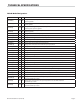
TECHNICAL SPECIFICATIONS Table B: Model Designations MODEL MM Ins DESCRIPTION MST42R(E) 864 34 Range with oven, two open top burners & a 432 mm wide solid hot plate or optional griddle MST42RC(E) 864 34 Range with convection oven, two open top burners & a 432 mm wide solid hot plate or option griddle MST42S(E) 864 34 Range with storage compartment, two open top burners & a 432 mm wide solid hot plate optional griddle MST42T(E) 864 34 Modular top with two open top burners & a 432 mm wide s
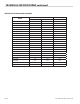
TECHNICAL SPECIFICATIONS continued MODEL MM Ins DESCRIPTION MST4S(E) 432 17 Range with storage base and two open top burners MST4T(E) 432 17 Modular top with two open top burners MST6S(E) 432 17 Range with 330 mm wide solid hot plate MST6T(E) 432 17 Modular top with 330 mm wide solid hot plate MST7S(E) 432 17 Range with 330 mm wide tap controlled griddle MST7T(E) 432 17 Modular top with 330 mm wide tap controlled griddle MST17B(E) 432 17 Char broiler MST24BT(E) 610 24 Char
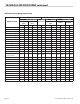
TECHNICAL SPECIFICATIONS continued Table C: Exterior Dimensions MODELS HEIGHT WIDTH DEPTH WEIGHT mm ins. mm ins. mm ins. kg lb MST42R(E) & RC(E) 952.5 37.5 863.6 34 965.2 38 235.9 520 MST42S(E) 952.5 37.5 863.6 34 965.2 38 222.3 490 MST42T(E) 317.5 12.5 863.6 34 965.2 38 99.8 220 MST43R(E) & RC(E) 882.6 34.75 863.6 34 965.2 38 213.2 470 MST43S(E) 882.6 34.75 863.6 34 965.2 38 158.8 350 MST43T(E) 247.6 9.75 863.6 34 965.2 38 99.
TECHNICAL SPECIFICATIONS continued Table D: Gas Flow Rate (Net) Per Model MODEL Page 8 2nd Family (m3/h) NET 3rd Family (kg/h) G20 @ 20mbar G25 @ 25mbar G31 @ 37/50mbar MST42R(E) & RC(E) 2.99 3.47 2.24 MST42S(E) & T(E) 1.87 2.18 1.4 MST43R(E) & RC(E) 5.14 5.97 3.35 MST43S(E) & T(E) 4.02 4.68 2.51 MST44R(E) & RC(E) 4.47 5.19 3.35 MST44S(E) & T(E) 3.35 3.9 2.51 MST45R(E) & RC(E) 3.35 3.9 2.51 MST45S(E) & T(E) 2.24 2.6 1.68 MST46R(E) & RC(E) 3.38 3.93 2.
TECHNICAL SPECIFICATIONS continued Table E: Heat Input (Gross) Per Burner / Burner Group MODELS / SECTION 2nd Family, Groups H,L & E 3rd Family, Group 3P (G20/G25 @ 20/25 mbar) Nat Gas (G31 @ 37/50 mbar) Propane Per burner / section Per burner / section kW MJ/HR kW MJ/HR MST40(E) Oven 11.72 42.2 11.72 42.20 MST40RC(E) Oven 11.72 42.2 10.3 36.90 MST42(E) Open Top 5.86 21.1 5.86 21.10 MST42(E) Solid Top/Griddle 7.91 28.48 7.91 28.48 MST43(E) Open Top 7.03 25.32 5.86 21.
TECHNICAL SPECIFICATIONS continued Table F: Pressure Setting / Injector Size 2nd Family, Groups H, L & E 3rd Family, Group 3P Setting Pressure MODEL/SECTION G20 @ 20 mbar Setting Pressure G25 & 25 mbar Injector Size G31 @ 37/50 mbar Injector Size 37 mbar 50 mbar mbar “WC mbar “WC DMS mm mbar “WC DMS mm DMS mm MST42(R,RC,S & T)(E) 20 8.0 25 10 – – 37/50 14.8/20 – – – – MST43(R,RC,S & T)(E) 20 8.0 25 10 – – 37/50 14.8/20 – – – – MST44(R,RC,S & T)(E) 20 8.
TECHNICAL SPECIFICATIONS continued Table G: Pressure Setting For Low Tap Position MODELS/SECTION 2nd Family, Groups H, L & E 3rd Family, Group 3P G20/G25 @ 20/25 mbar Natural Gas G31 @ 37/50 mbar Propane mbar mbar MST40(E) Oven 1.2 1.2 MST42(E) Hot ToP 2.0 3.0 MST42(E) Griddle 2.0 3.0 MST45(E) Hot Top 3.7 11.0 MST46(E) Hot Top 2.0 3.0 MST47(E) Griddle 2.0 3.0 MST54(E) Hot Top – – MST6(E) Hot Top 2.0 3.0 MST7(E) Griddle 2.0 3.0 MST(17,24,34)(E) Broiler 2.0 7.
TECHNICAL SPECIFICATIONS continued Table I: Australia Only Nominal Gas Consumption & Injector Sizes NATURAL GAS MODEL/SECTION PROPANE GAS INJ.DIA mm. MJ/H Gas Pressure (kPa) INJ.DIA mm MJ/H Gas Pressure (kPa) Standard Oven 3.25 42.20 1.0 1.70 36.90 2.49 Convection Oven 3.20 36.90 1 1.70 36.90 2.49 MST43 Open Top 2.35 25.30 1 1.40 21.10 2.49 MST4, 44 Open Top 2.64 36.90 1 1.78 36.90 2.49 MST5, 45 Front Fired Hot Top 1.70 12.30 1 1.07 12.30 2.
STATUTORY REGULATIONS The installation of this appliance must be carried out by a competent person and in accordance with the relevant regulations, standards, codes of practice and the related publications of the Country of destination. AUSTRALIA SPECIFIC CLAUSE This appliance must be installed in accordance with the manufacturers instructions, local gas fitting regulations and requirements of AS 5601 / AG 601 installation code.
INSTALLATION 1. Carefully remove unit from carton. The wires or ties retaining the burners and other packing material must be removed from the unit. Any protective material covering stainless steel parts must also be removed. 2. All equipment is shipped from the factory with legs fitted, unless otherwise specified. Where the range is to be mounted on a dais or cove base, it is shipped without legs. Legs must be fitted to the oven where it is installed on a combustible floor. 3.
COMMISSIONING Testing & Adjustments Burner Adjustments Fittings and pipe connections: Check all pipe fittings and connections to the appliance for leaks. Use only approved gas leak detectors or soap solutions to check fitting and pipe connections. DO NOT USE A FLAME. • Check that the air shutter is set to the required opening. Refer to Table H Figure 1 – Air Shutter 1. Turn all valves and thermostats to the OFF position. Fixing Screw 2.
COMMISSIONING continued Oven Thermostat Calibration Minimum flame setting: To check the calibration, follow this procedure: To obtain the minimum flame setting: A. Place the thermocouple of the test instrument or a mercury thermometer in the center of the oven. 1 Set the gas valve to the MIN position. B. Turn the oven control dial to 400°F (202°C) to allow the oven temperature to stabilize. Allow the oven to cycle twice before taking a test reading. C.
COMMISSIONING continued Figure 5 – Minimum Flame Setting Open Burners 1. Light the pilot light in accordance with the User’s Instructions. Gas Inlet Pilot Gas Outlet Pilot Adjuster Screw Min. Flame Adjusting Screw 2. Check that the length of the flame is correctly at 7-12mm and adjust as necessary. Figure 7 – Minimum Flame Setting Pilot Adjuster Gas Outlet Low Flame Adjuster For MST models only Broiler Burner Test Point To obtain the minimum flame setting: 1.
COMMISSIONING continued Solid Hot Plate/Griddle Fryer 1. Light the pilot light in accordance with the User’s Instructions. 1 Light the pilot light in accordance with the User’s Instructions. 2. Check that the length of the flame is 12mm aprox and adjust as necessary (see Figure 7). 2. Check that the length of the flame is approximately 12mm and adjust as necessary. Front Fired Hot Top When all the settings have been checked: 1. Light the pilot light in accordance with the User’s Instructions. 1.
OPERATION continued Standard Ovens Shut Down: 1. Push in the main/pilot gas valve and turn it counterclockwise to the IGNITION position. 1. Turn the thermostat OFF. 2. Lower the front kick panel. 2. Return the power switch to OFF. 3. Turn the oven valve OFF. 3. Holding the oven gas valve fully in, press the red piezo igniter button several times. Motor Care: 4. When the pilot burner is lit, continue holding down the oven gas valve for 20 seconds, then release it.
OPERATION continued Shut Down: Figure 9– Briquette Pattern 1. Turn all valves to the OFF position by rotating the knob clockwise 6 mm (1/4”) turn. 2 Steel bars If the unit is to be shut down for an extended time, close the in-line gas valve. NOTE: Suffix E models are equipped with an electric spark ignition module for pilot burner ignition. Pushing the spark button will ignite all pilot burners simultaneously.
OPERATION continued FRYER CONTROL CIRCUIT FOR MILLIVOLT SYSTEMS HI-LIMIT THERMOSTAT THERMOCOUPLE INSERT 1 SAFETY DRAIN SWITCH (OPTIONAL) THERMOPILE PILOT GENERATOR ON 1/2 P.S.I. Honeywell OFF PILOT HONEYWELL 1/2 P.S.I. PILOT ADJ. INSERT 2 ON/OFF SWITCH (OPTIONAL) FENWALL OPERATING THERMOSTAT MAINTENANCE AND CLEANING Proper maintenance, cleaning and care of cooking equipment is an important part of any program and will keep it in good operating condition.
MAINTENANCE AND CLEANING continued Cast Iron Top Grates And Ring Grates 1 Move the grates from the range and wash them in warm water with mild soap. Then dry them with a clean cloth. 2. Immediately after drying, season the grates lightly with a non-toxic oil (a light vegetable oil, liquid or spray). WARNING: Do not season top grates while they are still on the range top. A flash fire may result. 3. After seasoning, replace the top grates on the range and operate all the range top sections on LOW. 4.
MAINTENANCE AND CLEANING continued 1. After each use, clean the surface thoroughly with a grill scraper or spatula. Wipe off debris left over from the cooking process. 2. Daily: Clean the surface with a grill brick or pad. Remove, empty and clean the grease container thoroughly. 3. Weekly: Clean the surface well with a grill brick or pad. Rub with the grain of the metal while it is still warm. A detergent may be used on the plate surface to help clean it, but make sure it is removed.
MAINTENANCE AND CLEANING continued 4. Rotate the air shutter to obtain the following: a. Open (star) burner – 12 mm stable, sharp inner blue cones. Fryers 1. For daily cleaning, saturate cloth with full-strength Fryer and Griddle Cleaner and wipe while warm - rinse thoroughly 2. Clean frypot at least once each week by filling to just under full mark with water. Add Fryer and Griddle Cleaner according to size of fryer (one cup per 35 lbs. (16kg) of fat), bring to boil and continue boiling 10-15 minutes.
SERVICING Regular maintenance and servicing by competent and qualified personnel is recommended for the continued safe and efficient operation of cooking equipment. Solid Hot Plate/Griddle Burners WARNING: Before working on any appliance, SHUT OFF the gas supply at the main shut-off valve and electrical supply at the main disconnect. On completion of any servicing work, test for gas leaks before returning the equipment into service. 2. Lift the rear of the burner and slide it backwards off the orifice.
SERVICING continued 5. Slide the burner to the rear and off the orifice. Then slide it to the left and remove it from the combustion chamber. Oven 1. Open the drop-down lower kick panel. 6. Clean the burner in hot soapy water with a stiff scrubbing brush. 7. Rinse the burner and shake it well to remove the water. 2. On all models but RC units, remove the oven base plate. (To deal with RC models, follow the procedure specified for the burner cleaning instructions. 8.
SERVICING continued 1. Place the thermocouple of the test instrument in the center of the oven. 6. Remove the thermostat dial, making sure not to disturb the setting. 2. Light the oven, set the thermostat to 400°F (204°C) and wait 15 minutes for the oven temperature to stabilize. 7. Hold the calibration plate and loosen the two calibration locking screws. 3. Check the temperature at 5 minute intervals until three successive readings are within ±5°F (±3°C) of each other. 8.
REPLACEMENT OF PARTS For replacement parts, users and service personnel are referred to Garland’s Master Series Heavy-duty Ranges and Attachments parts list. This section of the service manual deals only with the replacement of parts on heavy duty cooking equipment. 7. Disconnect the oven gas supply pipe from the outlet of the thermostat. WARNING: Before servicing any cooking appliance be certain to SHUT OFF the gas supply at the shut-off valve and the electrical supply at the main disconnect.
REPLACEMENT OF PARTS continued Oven 3. Disconnect the wires from the valves on the ignition module. 1. Remove the screws securing the valve panel and remove the panel. 4. Remove the screws that secure the module. 2. Disconnect the thermocouple connection at the gas valve. 5. Replace with a new module and reassemble the unit in reverse order. 3. Disconnect the pilot tube connection at the gas valve or thermostat. Push Button Spark Switch Models With Suffix E 4. Open the lower kick panel. 1.
CONVERSION INSTRUCTIONS Servicing must be carried out by a competent person in accordance with the law. WARNING: Turn off the gas supply to the appliance at the service cock before commencing any servicing work. IMPORTANT: Test for gas soundness on completion of any servicing work. The following instructions are intended to describe the operations necessary to convert equipment from operation on one gas family to that of another. 1.
TROUBLE SHOOTING GUIDE Open Type Hot Plate, Solid Hot Top, Griddles And Broilers PROBLEM Burner flame too large. Burner flame soft-yellow tip. Flame lifts off burner ports. Flame lights back to injector. Burner ‘pops’ when turned off. Delayed ignition Pilot burner will not ignite. No spark to pilots. Pilot keeps going out. POSSIBLE CAUSE Incorrect setting pressure or injector. Insufficient primary air. Excessive primary air. Excessive primary air. Excessive primary air. Pilot flame too small.
TROUBLE SHOOTING GUIDE continued PROBLEM Low millivolt output on open circuit tests. Low millivolt output high in open circuit test, but low in closed circuit test. Millivolt output high on closed circuit test, but blame safety tap will not stay open. Door will not stay closed. Door will not stay open. Door not closing on one side. Door not level or low in center. POSSIBLE CAUSE Pilot flame too small. Defective thermocouple. SOLUTION Adjust pilot flame length. Replace thermocouple.
TROUBLE SHOOTING GUIDE continued Fryers PROBLEM Low millivolt output. POSSIBLE CAUSE Low pilot flame. Clogged pilot orifice. Low gas pressure. Manual shut-off partially closed. Flame blowing away from power pile. Pilot flame adjusted too high. Good output, but low reading at valve. Output high with main burner off-low with it on. Output good, but pilot magnet will not hold. Main burner will not come on though pilot remains lighted. Burner does not light all the way around. (Delayed ignition.
Installation, Operating & Service Manual MASTER SERIES HEAVY DUTY RANGES, FRYERS & BROILERS Garland Commercial Ranges http://www.garland-group.