GARLAND A WELBILT COMPANY BUILT TO LEAD...
This service manual is designed to answer questions related to model operational requirements, troubleshooting and disassembly/assembly procedures. It contains electronic ignition operation, troubleshooting and electronic control operations that include diagnostic codes, ladder diagrams, wire diagrams and troubleshooting. It also includes BTU ratings, orifice size and gas pressure technical data for each model.
SECTION 3: COMPONENT ACCESS OF FUNCTIONAL COMPONENTS.................................. 16 DOOR GASKET REPLACEMENT............................................................................................................................ 17 TO REMOVE DOORS FROM THE OVEN................................................................................................................ 18 INSTALLATION OF OVEN DOORS ...................................................................................................
GAS CONVECTION OVEN "GAS SPECIFICATIONS” MAIN BURNER ORIFICE TOTAL B.T.U.'S ORIFICE AMT. GAS PRES. W/C NAT PRO PILOT ORIFICE AMT. PILOT ORIFICE * NAT 40,000 MCO PRO NAT PRO ** 4.5" 5 /64” #55 2 .020" .012" 1 10.0" (.0781”) 60,000 MCO 5 /64” 5.0” 4.5" #55 3 .020" .012" 1 10.0" (.0781”) 80,000 MCO 5 /64” 5.1” 4.5" #55 4 .020" .012" 1 10.0" (.0781”) 5.5” * - Gas pressure measured at burner manifold. ** - Gas pressure measured at redundant gas valve pressure tap.
Understanding the sequence of operation is necessary in properly trouble-shooting this appliance. In this section the sequence of operation will be covered first, as well as calibration and operation of components, and basic trouble shooting techniques for that specific model. Follow each sequence carefully, and get to understand its operation before moving on to trouble shooting. MANUAL CONTROLS - "M" Sequence of Operation (Starting with the oven doors in closed position.) 1.
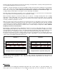
A thermocouple type test instrument is preferred for measuring oven temperatures accurately. Mercury thermometers are acceptable providing they can be proven accurate. Regardless of the type instrument used, it is most desirable to double-check it just before making an oven temperature check. This can be done simply and quickly by placing the thermocouple tip (or immersing the entire mercury thermometer) in boiling water. Note: Mercury oven thermometers should be the "total immersion type.
five times doubling the thickness with each fold. After the fifth fold, place the thermocouple tip in the center of the aluminum piece and fold once more. Finally, fold in the sides so that the foil clings to the thermocouple tip. A mercury thermometer can be weighted in much the same way by wrapping several layers of aluminum foil around the bulb end thus creating the necessary mass. This procedure is a must if you open an oven door to check temperature.
ELECTRONIC CONTROLS - “E” Sequence of Operation (With the Oven Doors Closed) COOK 1. Line Voltage is supplied to the Mode Switch, Door Switch and the Momentary Light Switch. 2. Set Mode Switch to COOK and close the oven doors. Line Voltage is sent from Mode Switch to power up the Controller and to the AUX relay on the controller. With the oven doors closed Line Voltage is sent to the 24 volt transformer. 3. Set desired temperature. The controller’s relays now close. 4.
ELECTRONIC CONTROL FAILURE CODES The GARLAND digital control has a self-diagnostic program. If a problem occurs within the digital controller, you may see one of the "F" codes. Below is a listing of the "F" codes with explanations: -F1- Relay output is enabled when not cooking. If this failure code appears in the display, the cook relay may be on even if the control is not cooking. The control should be replaced. -F2- Over temperature alarm.
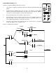
The controller needs voltage to operate and is capable of operating on three (3) different line voltages, 115 Vac, 208 Vac, 240 Vac. On the back of the Robertshaw COM6000 there are several ¼” male spade terminal or pin connections. The below is a drawing of the rear of a Robertshaw COM6000 Controller along with a definition of each of the pin connections.
The User Preference Offset is designed to enable the user to adjust the controlling temperature. There are two different styles of controllers used by GARLAND at the present time. They are the Robertshaw COM6000 and COM6700 Series. To determine which of the controllers you are working on, look at the back of the controller and you will see a sticker with a printed number like “PN:100-289-03”, below this number is the controller style number. For example: COMA-6704-GL.
Entry Exit UPO - User Preference Offset. Used by the user to adjust the controlling temperature +/- 50º in 1º increments. 1. 2. 3. 4. Set the time digits to 00:00. Set the temperature digits to X10º. Depress & hold the Start button for five seconds. “UPO” & Current UPO will be displayed. Turn TEMP or TIME dial to adjust. 1. Depress the Actual Temp button to lock-in. 1. Depress the Actual Temp button to lock-in. 1. Depress the Actual Temp button to lock-in. 1. Depress the Cancel button to lock-in.
The safety lockout timer circuit starts timing the moment the trial for pilot ignition starts. When the timing period runs out, the trial for ignition ends, and the control module goes into lockout. Before another attempt to start can be made, the S86 must be reset. Reset by adjusting the thermostat or controller or to its "OFF" position. An alternate method is to shut the system power "OFF". If normal ignition does not occur, use the trouble shooting table to determine the problem.
and answering conditions in each box encountered, until a problem and/or the repair is explained. After any maintenance or repair, the trouble shooting sequence should be repeated until the trouble shooting procedure ends with a normal system operation. START NOTE: Before troubleshooting, familiarize yourself with the startup and checkout procedure. TURN GAS SUPPLY OFF.
CHECK GROUNDING A common ground is required for the pilot burner, the ignitor-sensor, the GND terminal of the S86, and the main burner. The main burner generally serves as the common ground. If the ground is poor or erratic, safety shutdowns may occur occasionally even though operation is normal at the time of the checkout. Therefore, if nuisance shutdowns have been reported, be sure to check the grounding.
APPEARANCE CAUSE SMALL BLUE FLAME Check for lack of gas from: • Clogged orifice filter • Clogged pilot filter • Low gas supply pressure • Pilot adjustment at minimum LAZY YELLOW FLAME Check for lack of air from: • Large orifice • Dirty lint screen, if used • Dirty primary air opening, if there is one • Pilot adjustment at minimum WAVING BLUE FLAME Check for : • Excessive draft at pilot locations • Recirculating products of combustion NOISY LIFTING BLOWING FLAME HARD SHARP FLAME Check for: • High ga
This section will give you the best way to access component for replacement. COMPONENT LOCATIONS: Top Front Center Door Chain Door Catch Right Front Control Panel 24v Transformer, Ignition module Redundant gas valve Lower Front Door Micro-Switch Data Plate, Burner Package Inside Oven Oven Convection Motor Oven Interior Lights Single Deck (Front View) Door Gasket Replacement 1.
2. 3. 4. 5. Locate stainless steel door gasket, mounted to oven front frame. Remove the #10 Phillips sheet metal screw that attach the retainer to the oven's front frame. Remove stainless steel door gasket. Replace stainless steel door gasket and to reverse above procedure to re-install. 1 2 2 3 To Remove Doors from the Oven 1. Remove top front cap veneer.
2. 3. 4. 5. Remove door chain assembly (NOTE: The “A” model does not come equipped with door chain). Remove flat head metal screw 1/4”-20x1/2” from bearing retainer. Push the door toward hinge and lift up. NOTE: Bottom bearing retainer will stay in place. Remove the right door in the same manner. 1 2 3 FILE NAME JIT03459 4 To Reinstall Doors onto Convection Oven 1. 2. 3. Reverse procedure above. Close doors. Reinstall the door chain. 2 Links Installing and Adjusting Door Chain 4. 5. 6.
NOTICE: DEPENDENT DOOR SHOWN 6 3 7 4 5 8 2 7 1 7 To disassemble left door: 1. Once the door has been removed from the oven (refer to instructions on the previous page), remove the 12 truss head 10 x ½ Phillips screws . 2. Remove 2 allen head cap screws from the door handle . 3. Carefully pry off the door panel from the door window bezel . 4. Remove 2 hex head m.s. ¼ -20 x ½ from the door liner that attach hold down straps to the door liner . 5. Lift out the door frame . 6.
NOTICE: DEPENDENT RIGHT HAND DOOR SHOWN. 5 1 2 3 4 1. Once the door has been removed from the oven (refer to instructions on page 19), remove 9 truss head s.m.s. 10 x ½ from the top, bottom and left side (as shown) from the door panel . 2. Pry the door liner apart from the door panel . This will expose the door frame . 3. To reassemble, reverse above procedure.
To Replace or Adjust Door Latch Mechanism 1 1. Open oven doors. 2. Remove 2 pan head Phillips screws. 3. Lift door latch mechanism up and out of door assembly. 4. To adjust latch mechanism , loosen lock nut & and adjust by tightening or loosening adjustment nut. 3 6 To Replace Convection Oven Motor Assembly (Drawing Below) 2 1. Open doors and remove all oven racks. 2. Remove 4 #10 sheet metal screws (that secure air baffle) and remove air baffle. 3.
Assembly 6 2 1 3 7 5 5 FILE NAME JIT00012 4 9 8 1. Assemble motor mount plate, * insulation, motor mount plate inner together by fastening four flat head m.s. 1/4-20x2½" into the four holes noted on the above drawings. 2. Secure each flat head m.s. 1/4-20x2½" with a flat washer and three hex nuts 1/4-20 3. Attach motor mounting plate to motor . Insert the four flat head m.s. 1/4-20x2½" through the mounting tabs on motor as shown. Secure with two hex nuts 1/4-20 4.
Main Burner, Pilot Burner Removal & Door Micro Switch Location 3 4 2 1 To access the Burners, Pilot or Door Switch - remove the lower combustion chamber, (not show). This exposes these components, also you will note that the rating or data plate is on the inside of the combustion shroud. For ovens that are 80,000 B.T.U.’s there are four burners, 60,000 B.T.U.’s there are three burners as shown in the above illustration, and 40,000 B.T.U.’s there are two burners. On 40,000 B.T.U.
SECTION 4: - COMMON WIRE DIAGRAMS 25