SERVICE MANUAL FOR THE MODELS: MP-GS/GD-10-S Users are cautioned that maintenance and repairs must be performed by a Garland authorized service agent using genuine Garland replacement parts .
Page Part # MPSM07 (03/24/08)
TABLE OF CONTENTS Section One – Section Two – Service . . . . . . . . . . . . . . . . 39 Component Identification . . . . . . . . . . . . . . . . . . . 40 Operation & Installation Manual . . . . . . . 5 Moisture Control . . . . . . . . . . . . . . . . . . . . . . . . . Dimensions And Specifications . . . . . . . . . . . . . . . . 7 Cavity Temperature Controls . . . . . . . . . . . . .
Page Part # MPSM07 (03/24/08)
Section One – Operation & Installation Manual Part # MPSM07 (03/24/08) Page 5
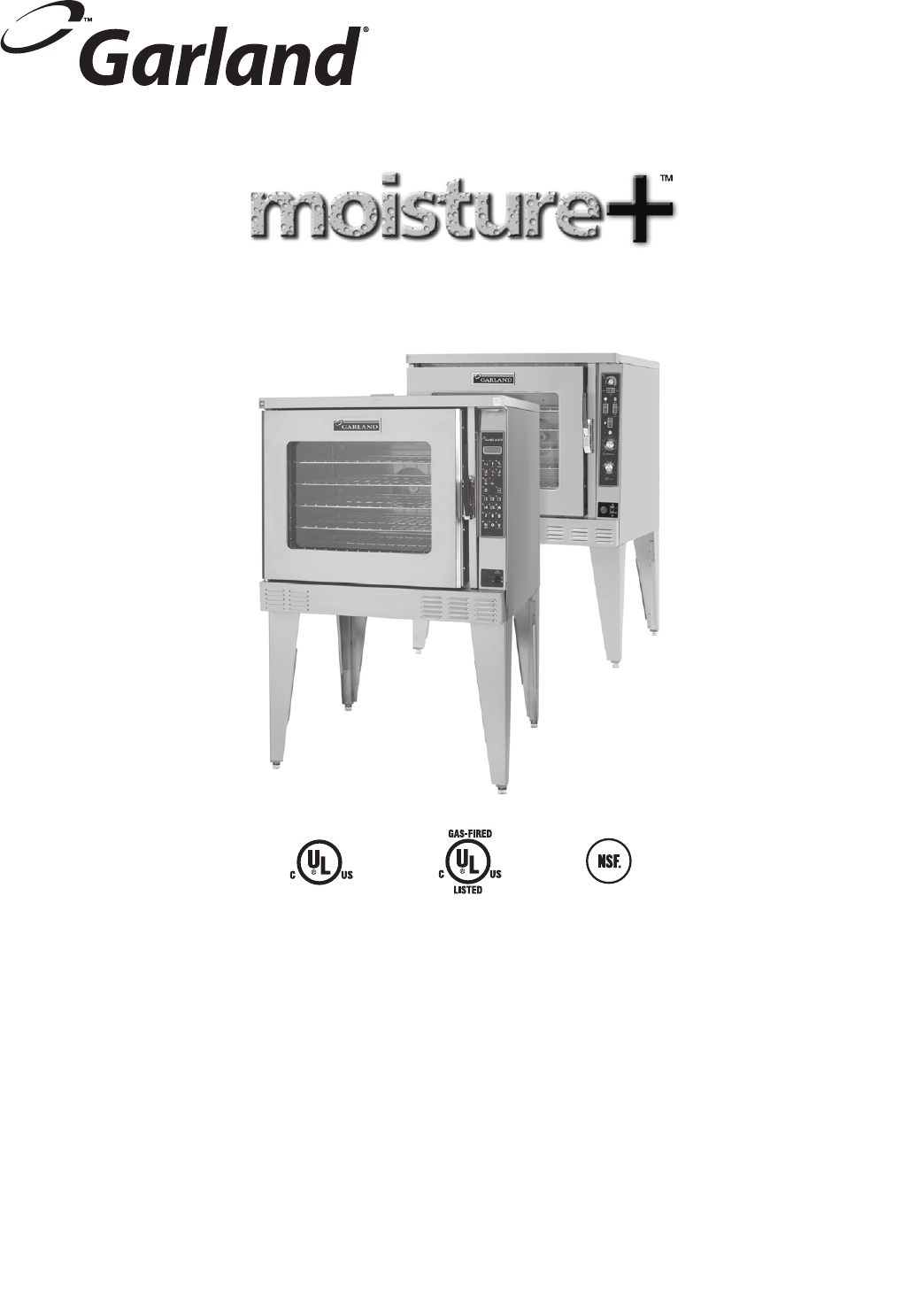
Congratulations! You have just purchased the latest in cooking technology, the new moisture+™ from Garland . Garland is an established leader in innovative oven technology, and has manufactured this multifunction oven with the operator in mind . The moisture+™ provides function not previously available in a convection oven . Your moisture+™ will operate as three pieces of equipment: a convection oven, a humidified baking oven, and a humidified cook & hold oven .
DIMENSIONS AND SPECIFICATIONS 2-1/4" [57mm] 32-3/4" [832mm] DOOR OPENING REQUIRED 38" [965mm] 2-1/4" [57mm] 32" [813mm] 32" [813mm] 70-1/4" [1784mm] 58.5" [1486mm] 32" [813mm] 26-1/2" [673mm] FLOOR LINE 6-1/4" [159mm] 40" [1015mm] ADD 4" [102mm] FOR DEEP OVENS Gas input ratings are for installations up to 2000 feet (610 m) above sea level. Specify altitudes above 2000 feet.
PREPARING THE OVEN FOR INSTALLATION Legs and Casters NOTE: If you will be installing an open base kit, please skip to the next page and proceed with the steps listed under “Open Base Assembly.” 1. (See Figure 1.). At the bottom end of each leg, install the bullet foot insert or caster insert. The fit of the insert to the leg is intended to be snug, tap them lightly into place with a mallet or rubber hammer. Install two #5 x 1/4” self-drilling, thread forming screws into each caster insert. 2.
PREPARING THE OVEN FOR INSTALLATION Open Base Assembly Use the following sequence of steps to assemble and install the open base accessory. 1. (See Figure 2.). Align the rack guide upper support to the corresponding holes in the oven base. Fasten using three #10 x 3/4” machine screws on each side of the oven. 2. At the lower end of each leg install an “L” shaped support clip using a #10 x 3/4” sheet metal screw. Do this before fastening the leg to the base. 3.
PREPARING THE OVEN FOR INSTALLATION Stacking Two Ovens 5. Remove the outer flue vent from the right top corner of the rear of each oven, saving the screws. 1. Follow the instructions in the section entitled, “Legs and Casters,” on page 5. Then resume at step 2 on this page to complete the stacking process. 6. If they are not already fastened together, assemble the two parts of the interconnecting flue channel included in the stacking kit, using six #10 x 3/4” sheet metal screws. 2.
INSTALLATION It is the responsibility of the purchaser to ensure the oven is installed in a manner to meet all local codes. In the absence of local codes, applicable national codes are referenced in this booklet. In the case of discrepancy between the information in this booklet and local codes, it is recommended you consult your local inspector(s). This appliance meets or exceeds all applicable regulations and standards in effect on its date of manufacture.
ELECTRICAL CONNECTIONS A separate electrical connection must be supplied for each oven. Connection to the electrical service must be grounded in accordance with local codes, or in the absence of local codes with the National Electrical Code, ANSI/NFPA 70, or the Canadian Electrical Code, CSA C22.2, as applicable. A strain relief for the power supply cord is required. The installer must supply a cord bushing that meets local and national codes. For 120VAC usage a cord and NEMA 5-15P plug is provided.
WATER CONNECTIONS It is the responsibility of the purchaser to install and maintain the water supply to the moisture+ oven. Failure to provide satisfactory water quality to operate the oven properly can cause damage to integral components and void your warranty. This oven must be installed to comply with the applicable federal, state, or local plumbing codes. Water supply connection to the moisture+ is made via a 1/8” NPTF fitting at the rear of the oven.
VENTILATION AND AIR SUPPLY Proper ventilation is highly important for effective operation. There are only two choices for properly venting an oven: 1) canopy hood, or, 2) direct venting. The ideal method of venting a gas oven is through the use of a properly designed canopy hood. The hood should extend beyond all sides of the oven 6 inches, (150 mm), and be installed at least 78 inches, (1950mm), from the floor. A strong exhaust fan will create a vacuum in the room.
GAS MODEL TESTING & LIGHTING INSTRUCTIONS Turn on the main gas valve. Remove the lower front trim cover. Drop the control panel and leak test all fittings and connections upstream from the service valve located on the redundant combination gas valve. Should any gas leaks be detected turn OFF the main gas valve, correct the problem and begin the test again. Remove the blanking plug from the manifold test spigot and connect a pressure test gauge.
EXPLANATION OF CONTROLS (Standard Models) Mechanical Control, (Standard Models) Moisture Control This controls the duration of the moisture injection into the oven cavity. This is a rotary dial. Moisture Switch This rocker switch has three positions. The center position is OFF. This shuts off electrical power to the moisture system. The AUTO position energizes the system until the switch is turned off. This activates the injecting timer at the intervals manually set with the moisture control.
OPERATING INSTRUCTIONS, (Standard Models) In Off Mode When the oven is off, there are no lights or indicators. The oven interior light will operate. Start Up Press the Cook/Off/Cool Down rocker switch to the COOK position. The green lamp will light indicating the oven is powered in cook mode. The oven will begin to heat to the temperature set on the thermostat dial. The amber lamp will light indicating the heat is active.
EXPLANATION OF CONTROLS, (Deluxe Models) Programmable Control, (Deluxe Models) Display Five distinct areas of the LED display screen are common to most programming modes and cooking modes: 1. Upper left corner: displays the programmed temperature followed by the word SET. 2. Lower left corner: displays actual temperature currently monitored by the control, (cavity or probe), followed by the letters ACT. 3. Upper right corner: displays time in hours, minutes and seconds; (00:00:00). 4.
High Fan Start/Cancel Pressing this key once will change the fan mode to high speed. The LED will light as a visual indicator that the fan is operating at high speed. Pressing this key begins or ends a cook cycle. When in the idle mode, pressing the key once will activate the timer to the last programmed time period. The display timer will count down the time remaining. Low Fan Pressing this key once will change the fan mode to low speed.
OPERATING INSTRUCTIONS, (Deluxe Models) Programmable Control (Deluxe Models) The design of the moisture+ and its controls allow the use of various operational feature sets alone or in combination: traditional (manual), or cook & hold, with or without a core probe, with or without moisture. Refer to the section entitled DISPLAY MESSAGES on page 23 for additional information regarding display messages and related button sequences.
Enter a number between 150 and 500, (factory default is 300). If a number outside this range is entered, the control will sound an error tone and reset to the closest allowable number within the range. 3. Press the Program key a second time. This stores and implements the temperature setting. The display will indicate PROGRAM COOK TIME. Use the numeric keys to enter the desired cooking time in hours, minutes and seconds. Each time a key is pressed, the numbers displayed move one position left.
Note: When the door is opened for loading, the internal temperature is likely to drop below the ready range. This is expected. The control allows 3 minutes for a user to load the product, close the door and press the Start/Cancel key to engage the timer. During this time, the control will ignore the drop in temperature.
Programming Recipe Keys For “one touch” cooking, each of the numeric keys, (1 through 9), on the keypad can be programmed to contain a product recipe consisting of 1 to 6 “profiles.” Each profile consists of a set of cooking parameters which control that profile’s fan speed, cook temperature, cook time and moisture settings. To program a recipe key: 1. Press and hold the Program key for 3 seconds. The display will indicate ENTER CODE. Here, a pass code must be entered.
Cooking With a Recipe Key 1. If the oven is in Off Mode, press the On/Off key once. 2. Press the numeric key that has been assigned to the desired recipe. This will begin the heating cycle. 3. Allow the oven to heat to the set temperature programmed in Profile 1 of the recipe. When the programmed temperature has been reached, the display will indicate READY. 4. Load the oven and close the door. Press the numeric key that has been assigned to the desired recipe. That key’s LED will light.
Repeat steps 4 through 7 for each individual shelf position/shelf timer key that will be used. 9. After programming all the shelf timers that will be used, press the Program key. This will return the oven to idle mode. Cooking with shelf timers: 1. Press the numeric key corresponding to the desired profile, (fan setting, temperature and time; see ‘To program shelf timers:’ on the previous page). Allow the oven to heat to the programmed temperature.
When the oven is in start-up, idling mode, during a cook cycle or holding product and door switch one is sensed the heat and motor are shut off and the display changes to tell the operator to close the door so operation can continue. When the oven is heating to a programmed temperature, particularly at start-up, this message is displayed. The programmed temperature being heated to and the actual temperature are shown (100º minimum).
When the oven is in Cool Down or Auto Cool Down modes the display will show this message. It indicates the oven is cooling and shows the actual temperature of the cavity. While in Cool Down, if the door is open too far, as sensed by door switch two, this message is displayed to prompt the user to close the door to the desired open range so the fan and motor will turn back on to finish the cool down.
When programming a recipe key, the display will prompt for the fan speed for the profile being programmed. The user scrolls through the list of choices and presses the Enter key to store the selection. The profile number is shown in the lower left corner of the display. When programming a recipe key, the display will prompt for the cook temperature for the profile being programmed. The profile number is shown in the lower left corner of the display.
COOKING WITH MOISTURE A key feature of the moisture+ is the ability to inject moisture into the oven cavity during operation. Typically, this results in shorter cook times, greater yield and improved texture, flavor and appearance of food products. The moisture+ system offers several methods for controlling moisture injection. While these functions provide a great degree of flexibility, it is possible to program settings for a product or cook cycle that will produce excessive moisture.
MOISTURE + COOKING GUIDE The following suggested times, temperatures and moisture settings are provided as a starting point only. Elevation, atmospheric conditions, gas supply, recipe, cooking pans, oven loads, and personal preference may affect you actual results. Product Temp Fan Speed Time Deluxe Control Moisture Setting Standard Control Moisture Setting Chicken Breasts – Fresh 6 Oz. – 9 Per Tray 325 F High 14 Min Poultry 58 Chicken Parts – Fresh Appox.
Temp Fan Speed Time Deluxe Control Moisture Setting Standard Control Moisture Setting Kaiser Rolls 325 F Low 8 Min Bread Max, Moisture for First Few Min. Of Bake, Then No Moisture Rolls – Crusty Dinner 35 gr. 350 F Low 10 Min Bread Max, Moisture for First Few Min. Of Bake, Then No Moisture Bread – Parisian 325 F High 17 Min Bread Max, Moisture for First Few Min. Of Bake, Then No Moisture Bread – Crusty Parisian 510 gr.
PERFORMANCE RECOMMENDATIONS Preheat the oven thoroughly (approx. 20 minutes) before use. As a general rule, the temperature should be reduced 25° to 50°F from that used in a standard/conventional oven. Cooking time may also be shorter. Close monitoring of the first batch of each product prepared is recommended. Cooking times and temperatures will vary depending upon such factors load size, mixture of products, moisture level, density and initial temperature of products.
TEMPERATURE CALIBRATION 1. Press and hold “PROGRAM” Button for three (3) seconds. When prompted, enter the Diagnostics Code 3-4-2-4, Press “Y”. The Moisture Plus part number will display briefly followed by the Diagnostic Tests – Keypad Test. 4. Press and hold the “PHANTOM” button for three, (3), seconds. The display will show the Actual Temperature on the first line and Set Temperature on the second line.
PROBLEMS / SOLUTIONS Problem Solution If cakes are dark on the sides and not done in the center . . . . . . . . . . . . . . . . . . . . Lower oven temperature If cakes edges are too brown . . . . . . . . . . . . . . . . Reduce number of pans or lower oven temperature. If cakes have light outer color . . . . . . . . . . . . . . . Rise temperature. If cakes settles slightly in the center . . . . . . . . . . . Bake longer or rise oven temperature slightly.
CLEANING NOTE: Disconnect the oven from the power supply before cleaning or servicing. Break-In Period When the oven is new, operate it for one hour at 450°F before beginning normal cooking operation. After cooling, wipe the interior, including the racks, with a clean damp cloth. Exterior Cleaning Establish a regular cleaning schedule. Spills should be wiped off immediately. The oven should always be allowed to cool sufficiently before any cleaning is attempted.
MAINTENANCE Users are cautioned that maintenance and repairs must be performed by a Garland authorized service agent using genuine Garland replacement parts. Garland will have no obligation with respect to any product that has been improperly installed, adjusted, operated or not maintained in accordance with national and local codes or installation instructions provided with the product. With minor periodic maintenance your Garland oven should provide satisfactory performance for many years.
REPLACEMENT PARTS Refer to the specific parts catalogue for the model oven that you own for a complete breakdown of all replacement component parts. The following is a partial list of the most commonly replaced functional parts. This list is provided for your reference only. Because specifications are subject to change without notice, be sure to check with your authorized service agent or the Garland Parts/Service Department to verify you are ordering the correct replacement part number.
Page 38 Part # MPSM07 (03/24/08)
Section Two – Service Part # MPSM07 (03/24/08) Page 39
COMPONENT IDENTIFICATION Moisture Control Mechanical Moisture Control • The Moisture system applies water through the solenoid in 1 second cycles. • The scale settings are in seconds. • Set to the low position, the water will cycle once every 60 seconds. • Set to the 60 second position, the water will cycle 6 times in 1 minute.
COMPONENT IDENTIFICATION Cavity Temperature Controls Service Overview • Spritzer (Water Inlet) – Purpose: This temperature switch assures water injection will not be available below a cavity temperature that would allow excessive puddle buildup on the cavity floor. The switch will close at a temperature of 225°F on rise. This low, but slightly above superheat value of water temperature will enable a preference of low temperature cooking.
COMPONENT IDENTIFICATION Component moveable service drawer.
DIAGNOSTIC PROCEDURES Diagnostics Mode To enter Diagnostics Mode, press and hold the Program (“Phantom” key lower right blank) button for three, (3), seconds. This key is located to the right of the Cook/Hold key as shown. When prompted, enter the code: 3-4-2-4 using the buttons 1 – 0. Press “ENTER” (Yes key). • After entering the code, and pressing “ENTER,” the Moisture Plus Part Number will be displayed briefly, and then the display will change to Diagnostics.
DIAGNOSTIC PROCEDURES Fan Speed Test 1. After selecting Fan Speed Test and pressing “ENTER” (lower right blank), the control will turn the oven fan on LOW speed for ten seconds. Verify that the fan is indeed running on low speed. The control will show 3. After a few seconds, the Moisture Test will complete. Press “CANCEL” to return to Diagnostics Mode. Temperature Calibration 2. After a short while, the control will turn the fan on HIGH speed for ten seconds. Verify that the fan is indeed on high. 1.
DIAGNOSTIC PROCEDURES • If the actual temperature inside the oven exceeds the set temperature by 50°F, the display will show “HI TEMP” and the alarm will sound. The fan will continue to run, however, power to the heaters will be cut. • NOTE: The control will need a complete power down and restart (unplug/plug in oven) before any control functions will become operational. If the problem persists, contact a service technician.
TESTING & TROUBLESHOOTING MP-GS-10/20 Troubleshooting Guide Use this chart with the appropriate wiring diagram, also found in this manual Mechanical Control PROBLEM Fan will not Run POSSIBLE CAUSE CORRECTIVE ACTION No Power to Oven Turn power on No Power to Oven Check Light circuit – IF OK, Select “Cook” and Check Timer circuit. IF OK, Check Door Micro Switches Micro switch not OPENING Check connections & switch functions. (Caution: the switch components on this control system pass 115 v. a.c.
Part # MPSM07 (03/24/08) Page 47 Does the product cook correctly? Yes Does the unit heat up? Baking Cavity Checks. No No Restart Oven: ( Control panel on ) • Observe automatic call for heat if oven cavity was cool. • Verify Convection Blower motor is up to speed. • Insure temp. quickly increases to set temp. Preliminary Checks Yes • Check probe for cleanliness , security, and circuit for proper resistance value changes per probe chart.
TESTING & TROUBLESHOOTING Key Pad / Ribbon Connector Test Points 11 10 9 Page 48 8 7 6 5 4 3 2 1 Key Ribbon Test Points Moisture 1&4 Light 2&4 On/Off 3&4 High Fan 3&5 Low Fan 2&5 Pulse Fan 1&5 Cool Down 3&6 Cook & Hold 2&6 Hidden 1&6 Start - Cancel 3&7 Blank 2&7 Program 1&7 1 3&8 2 2&8 3 1&8 4 3&9 5 2&9 6 1&9 7 3 & 10 8 2 & 10 9 1 & 10 N 3 & 11 0 2 & 11 Y 1 & 11 Part # MPSM07 (03/24/08)
TESTING & TROUBLESHOOTING Relay Board Component Identification Relay Relay Output K1 Light K2 Fan High K3 Fan Low K4 Heat demand K5 Spritzer K6 Cooling Fan K7 Not used K8 Not used K9 Not used + + + + + + + + + Relay Board All functions of the deluxe control are provided by electrical connections to the relay board. An electronic signal is transmitted from the control board to the relay board.
TESTING & TROUBLESHOOTING Inputs There are two input tabs to accept 24VAC from the relay board transformer (TR1). There are two 2 wire connections, one for each door switch connection Page 50 There are two sense lines. This circuit is internal, and signals the control to turn on the “HEAT” message in the lower right corner of the display. One circuit is for gas ovens, the second is for electric ovens. Both will use the same common terminal.
TESTING & TROUBLESHOOTING Outputs There is one 3 amp output for the control compartment cooling fan. This output will be controlled by the On/Off key on the control panel. It will also be active if the control goes into Cool Down There is one 10 amp relay for switching the heat circuit on and off as required There are two 30 amp relay connections, one each to switch the motor between high and low speed.
TESTING & TROUBLESHOOTING Test Points To aid in the troubleshooting of the control system there will be test points available for all relay board circuits. Used in conjunction with step by step instructions in the service manual, a technician will be able to quickly and easily trace a circuit to find a failure. Each circuit on the relay board will provide a solder filled plated through hole accessible to a DVOM probe tip. This will allow the technician to probe a circuit without disassembly.
TESTING & TROUBLESHOOTING Component Readings Garland sets the wheel at the factory with a specific gap setting. Spritzer Solenoid Valve Coil Resistance 22 Ω Direct Spark Ignition Module GROUND 5 Dual Stage Gas Valve Solenoid Resistance Pilot Valve = 28 .5 Ω LED THS 2 3 Trials 4 Seconds Per Trial No Retry Minimum Acceptable µa Reading ≥ 0 .3 M.V. 3 SENSE 4 Main Valve = 28 Ω Fan Motor And Blower Wheel Heat & Control Board Transformer Primary = 21 .5 Ω Secondary = 1 .
TESTING & TROUBLESHOOTING Direct Spark Ignition Detail MPO Direct Spark Ignition Specifications and Module Box Connections Manufacturer JOHNSON CONTROLS INC. Vendor Part # G760BAD-1 Ignition Type Direct Spark High Voltage Cable Wire Stranded Ignition Source High Voltage Spark Maximum Cable Length 48” (1,220mm) Flame Detection Means Flame Rectification Flame Detection Types Remote Sensing Minimum Flame Current 0.3 Microampere Flame Failure Response Time 0.8 Seconds Maximum Spark Gap 0.
PART NUMBER ITEM 3 4521570 2 1 2 1 L1 4 5 6 3 5 71A 77A 5 10 22 67 DESCRIPTION WIRE DIAGRAM - 115V GAS J5 P5 MAN-OFF-AUTO (WIRING SIDE) 1 76A 2 1 9 OVEN LIGHT S13 WATER THERMO.
R ES HEAT Part # MPSM07 (03/24/08) DESCRIPTION WIRE DIAGRAM - 115V GAS COOL FERRITES 27 26 28 29 2 SW 1 9 24VAC J1 T1 SW 2 T2 0 REV PROBE T9 T10 T8 K1 7 2 17 10 72 T23 ELEC COM. 21 T24 GAS 14 SENSE PCB 2 K2 P2 S2 TR1 P1 S1 19 CORE T7 COM 14 N.O. N.C. N.C. N.O.
SERVICE PROCEDURES (REMOVAL/REPLACEMENT) Oven Door Service – Removal / Installation 1. Disconnect power to unit. 2. . Locate and remove the 2 machine screws located on the lower upper LEFT side of the cavity frame. (These screws are just RIGHT of the lower door post on the cavity door frame.) 3. Start to remove this screw. ENSURE THAT THE DOOR IS SUPPORTED. Upper BA adjustable door mount plate Lower BA door support plate 6.
SERVICE PROCEDURES (REMOVAL/REPLACEMENT) 8. Test door switch activation / operation as indicated in the diagnostic checks. 9. If the door switch assembly requires adjustment, position the door to the full close position. Loosen the assembly mount screws just enough to set the switch stricker arm rollers at a position where there is no pressure on the rollers at either cam surface. 10. At that point, tighten the switch assembly bracket screws. 11. Run the door position diagnostic check again. 6.
SERVICE PROCEDURES (REMOVAL/REPLACEMENT) 4 To gain access, remove the screws holding the panel in place . BA plate secured to outer mount hole increases pressure on cavity seal 5 . Pull the panel towards the back of the oven to remove . 6 . Cavity probe is located ABOVE and to the RIGHT of the cavity motor . 7 . Disconnect the 2 BROWN probe wires at the temperature probe . 8 . The probe can now be removed from inside the oven . 9 . Reinstall the replacement probe in reverse manner . Fig .
Page 60 Part # MPSM07 (03/24/08)
Section Three – Parts List Part # MPSM07 (03/24/08) Page 61
DELUXE CONTROL PANEL MOISTURE PLUS (GAS) 2006 Deluxe Control Panel (Gas) Page 62 Part # MPSM07 (03/24/08)
GARLAND PARTS IDENTIFICATION Electronic Deluxe Control Panel (Gas) ITEM PART # 1 4521282 2 4522757 DESCRIPTION Kit Panel, Elec 475+ Ctrl Gas (Complete Assembly) Included Items; 2, 7,8,10,11,12,13,14 Kit - Panel & Overlay - 475+ Control Included Items; 5,6,9 5 4521366 Overlay - M+ General Market 6 4521283 B/A Panel - Control Mounting 7 4521281 W/A Panel - Electronic Control M+ 8 4521634 PCB, 475+ Programmable Control 9 — Membrane - Not Sold Separately 10 4521365 Underlay Card-M+ General Market 11 1955
STANDARD CONTROL PANEL MOISTURE PLUS (GAS) (MECHANICAL CONTROL) 2006 Standard Control Panel (Gas) Page 64 Part # MPSM07 (03/24/08)
GARLAND PARTS IDENTIFICATION Standard Control Panel (Mechanical Control) ITEM PART # 1A 4522831 1B 4521284 DESCRIPTION Kit Mech Ctrl Panel 3 Hr Timer Gas Included Items: 5,6,7,8,9,10,11,12a,15,16,17,19,20,21,22, 23,24,25,26,27a B/A Panel Assy - Mech 200 Ctrl (1) Hr Timer Gas Included Items: 5,6,7,8,9,10,11,12b,15,16,17,19,20,21,22 ,23,24,25,26,27b 5 4521286 Panel Stud Assy, Mech Control 200 6 1792901 Potentiometer, 2.
BURNERS & GAS COMPONENTS 2006 Burners & Gas Components Page 66 Part # MPSM07 (03/24/08)
GARLAND PARTS IDENTIFICATION Burner & Gas Components ITEM PART # DESCRIPTION 1 1916199 W/A Tail Pipe - Standard 2 1916198 W/A Tail Pipe - Deep 3 1026703 1/2 X 90 Degree Elbow 4 1004646 Short Nipple 1/2 NPT X 4 5 1004645 Short Nipple 1/2 NPT X 3-1/2 6 4521708 Valve, Ball Shutoff 1/2” NPT 7 1026733 1/2 NPT Street Elbow 90 Deg 8 1026903 Union 1/2 NPT - Raw 9 1004640 Close Nipple 1/2 NPT X 1 10 4520691 Bracket, Gas Valve Mtg 11 1754901 Valve - Basotrol Dual (G96) Nat Gas 12 1754902 Valve - Basotrol Dual (G96) L
INTERIOR COMPONENTS MOISTURE PLUS (GAS) Revised_Interior Componets Gas Page 68 Part # MPSM07 (03/24/08)
GARLAND PARTS IDENTIFICATION Interior Components - Gas ITEM PART # DESCRIPTION Oven Vent Cap – 60K BTU 1 1784302 Propane Gas 4518320 Motor Assembly – 208/240 Volt 2 4518319 Motor Assembly – 120 Volt Motor or Motor Wheel Not Available Separately 3 4521019 Frame, Light Box Cover 4 1676901 Glass – Duplate 5 4521022 Gasket – Light Glass 6 1025801 Socket Lamp, R7S 1623901 Lamp – 100 Watt, 120 Volt 7 1623902 Lamp – 100 Watt, 208/240 Volt 8 1906002 Probe – Flange Mount 8A* 1906003 Probe Extension Cable 9 1933407
DOOR COMPONENTS - GAS MOISTURE + OUTER DOOR ONLY INNER DOOR NO HANDLE COMPLETE DOOR WITH HANDLE 2006 Door Components (Gas) Page 70 Part # MPSM07 (03/24/08)
GARLAND PARTS IDENTIFICATION Door Components ITEM 1A 1B 1C 2 2A PART # DESCRIPTION QTY 4522138 Outer Door Assembly 1 4522755 Kit Mp Inner Door Without Handle 1 4522331 Door Assembly W/window - Mechanical Handle 1 1936301 Handle Door Edgemount M+ Complete W/Catch 1 4522371 Kit - Magnetic To Mechanical Door Handle 1 Note: Magnetic Handle P/N 4521255 NLA.
DOOR COMPONENTS - GAS MOISTURE + Revised_Plumbing Components (Gas) Page 72 Part # MPSM07 (03/24/08)
GARLAND PARTS IDENTIFICATION Plumbing Components (Gas) ITEM PART # DESCRIPTION 1 4521609 W/A Tubing Cavity Spritz 2 4517477 Grommet, H2O Line .
EXTERIOR COMPONENTS - GAS MOISTURE PLUS Revised_Exterior Components (Gas) Page 74 Part # MPSM07 (03/24/08)
GARLAND PARTS IDENTIFICATION Main Exterior ITEM 1 2 3 4 6 8 9 10 11 12 13 14 15 16 17 18 19* 20 PART # 1925301 1920002 1920201 1936999 4521061 1931801 4520867 4520866 1927199 1927197 1927195 1236100 1949701 1775102 1926501 1926502 1926521 1926522 1926531 1926532 1926802 1927002 1927101 1926902 DESCRIPTION Cover – Upper Trim Cover – Main Top Cover – Body Side, Left Outer Vent Assembly Cover – Body Side, Right Cover – Control Panel Left Cover – Lower Trim (Hose Option) Cover – Lower Trim (No Hose Option) Le
GARLAND PARTS IDENTIFICATION Wire Diagrams & Harnesses PART # DESCRIPTION Model Wire Diagrams 4521570 4521571 W/D 115V 60HZ Gas Mech Control W/D 115V 60HZ Gas Fast Control Standard Deluxe Wire Harness 1935002 W/H - Core Probe 1936074 W/H - Door Switches, Mech 1936076 W/H - Relay Board To Control 4521642 W/H Lights 4521645 W/H Door Switches Electronic 4521574 W/H Main Wiring 115V Gas 4521575 W/H Relay Card 4521576 W/H Solenoid 4521640 W/H Water Control 200 Control 4521854 W/H Control Panel Mech * NOT I
Part # MPSM07 (03/24/08) Page 77
Page 78 Part # MPSM07 (03/24/08)
Part # MPSM07 (03/24/08) Page 79