Apollo Model SL30 NAV/COMM Installation Manual August 2003 560-0404-03a
2003 Garmin AT, Inc. All rights reserved. Printed in the USA No part of this document may be transmitted, reproduced, or copied in any form or by any means without the prior written consent of Garmin AT, Inc. Due to Garmin AT’s commitment to constantly improve the quality and performance of our products, information contained in this document is subject to change without notice. Garmin AT, Inc. and Apollo are registered trademarks of Garmin AT, Inc. Garmin AT, Inc. PO Box 13549 Salem, OR 97309 Phone 503.
HISTORY OF REVISIONS Revision -01 Date 11/16/99 2/10/00 02 8/2/01 03 03a 2/21/02 8/26/03 Description Initial release (EN6278). Added interface wiring diagrams, refined post installation checkout procedures. New mounting tubes, dual SL30’s, DST info to Apollo GX (EN 6949). SW Version 1.2 Added helicopter environmental qualification information. Changed logo and added JTSO information. IMPORTANT NOTE “The conditions and tests required for TSO approval of this article are minimum performance standards.
NOTES
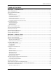
Table of Contents TABLE OF CONTENTS SECTION 1 - INTRODUCTION ................................................................................................ 1 ABOUT THIS MANUAL ..................................................................................................................... 1 APOLLO SL30 DESCRIPTION ............................................................................................................ 1 FEATURES .....................................................................
Table of Contents SETUP AND CHECKOUT............................................................................................................................................ 33 FINAL SYSTEM CHECK ............................................................................................................................................ 37 INSTRUCTIONS FOR CONTINUED AIRWORTHINESS ..........................................................................40 SECTION 3 - SPECIFICATIONS .......................
Table of Contents MESSAGE DEFINITIONS .................................................................................................................. 61 INPUT MESSAGES .....................................................................................................................................................61 REMOTE VOR LIST ..................................................................................................................................................62 REMOTE LOCALIZER LIST ..
Table of Contents LIST OF TABLES TABLE 1 - PACKAGE CONTENTS........................................................................................................5 TABLE 2 - COMM INTERFACE CONNECTOR PINOUT ........................................................................47 TABLE 3 - REAR PANEL CONNECTOR PINOUT .................................................................................48 TABLE 4 - TROUBLESHOOTING GUIDE ...........................................................................
Introduction SECTION 1 - INTRODUCTION ABOUT THIS MANUAL This manual describes the installation of the Apollo SL30 Nav/Comm units. It is intended for use by persons certified by the Federal Aviation Administration (FAA) to install aircraft navigation devices. It includes installation and checkout procedures for the SL30 unit to standards described in FAA advisory circulars AC 20-67B (for Comm). Section 1 Provides an introduction to the Apollo SL30 unit.
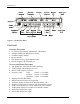
Introduction Figure 1 - SL30 Front Panel FEATURES GENERAL FEATURES • • • • • • 32 character high-intensity alphanumeric LED display Sunlight readable full alphanumeric display Automatic display intensity Back-lit buttons 200 channel memory (stored alphabetically) Remote frequency flip-flop input pin NAVIGATION RADIO FEATURES • • • • • • • • • • • • 2 200 channel Nav with solid state DSP technology VOR/Localizer and Glideslope receivers Built-in VOR/Localizer converter Frequency range: VOR 108.
Introduction • • • Internal RF diplexor Active and standby flip/flop frequencies DME tuning and data display COMM RADIO FEATURES • • • • • • • • • • • • 760 communications channels Frequency range 118 to 136.
Introduction SYSTEM INTERFACES NAVIGATION RECEIVER The SL30 can be installed in several configurations based upon individual requirements. This includes with or without an external course deviation indicator. The CDI may be discrete, serial, or composite.
Introduction UNPACKING THE EQUIPMENT Carefully unpack the equipment. Visually inspect the package contents for any evidence of shipping damage. Retain all shipping containers and packaging material in case reshipment is necessary. PACKAGE CONTENTS As shipped from the Garmin AT factory, the Apollo SL30 package includes most items necessary for installation other than supplies normally available at the installation shop, such as wire and cable ties, and required input and output equipment.
Introduction OTHER REQUIRED MATERIALS The SL30 is intended for use with standard aviation accessories. External devices required for various installations are listed below.
Introduction LICENSE REQUIREMENTS An aircraft radio station license may be required for operation of the SL30 Comm transmitter once installed in the aircraft. An application must be submitted on FCC Form 404, Form 605 or later revised application, which may be obtained from the FCC in Washington, DC, or any of its field offices. Procedures for applications are in CFR 47, Part 87, Aviation Services, Subpart B, Applications and Licenses.
Introduction NOTES 8 Apollo SL30 Installation Manual
Installation SECTION 2 - INSTALLATION This section describes the installation of the SL30 including mounting, wiring, and connections. A post installation check-out procedure is included at the end of this section. PRE-INSTALLATION INFORMATION Always follow good avionics installation practices per FAA Advisory Circulars (AC) 43.131B, 43.13-2A, and AC 20-67B, or later FAA approved revisions of these documents.
Installation 3. The valid flag sensitivity shall be 125 mV ± 10% for the flag to leave the stop and 260 mV ± 10% maximum for flag to be fully concealed. 4. The To/From flag shall have an input impedance of 200 ohms ± 10% and a sensitivity of ± 40 mV ± 15% at 25oC with flag fully in view. 5. The OBS resolver should be compatible with a standard 6-wire OBS interface: H ...........Reference output high C............Reference output low D ...........S1 COS input high E............S3 COS input low F ............
Installation dimples help maintain the proper clearance. The mounting tube must be installed with the clearance dimples pointing up. The mounting tube should be flush to the instrument panel and allow sufficient clearance for the back of the bezel of the unit to mount flush to the mounting tube. Sufficient clearance must exist in the instrument panel opening to allow ease of insertion and removal of the unit.
Installation UNIT INSERTION Position the cam lock as shown below. The front lobe of the cam should be vertical. The cam lock mechanism should be fully unscrewed (turned counter-clockwise). Slide the unit into the frame. Turn (clockwise) and carefully hand-tighten (4 in-lb max.) the cam lock mechanism using only the 3/32" hex driver provided in the installation package. Using a larger tool than the one provided makes it easy to exceed the allowable torque on the cam lock resulting in damage to the unit.
Installation Figure 4 - Mounting Frame Assembly Figure 5 - Cable Routing Apollo SL30 Installation Manual 13
Installation ELECTRICAL CONNECTIONS The SL30 installation kit includes 15- and 37-pin d-sub shells and crimp contacts. The crimp contacts are specified for 20 to 24 awg wire. Make the crimp connections with a crimp tool as specified on page 6. All wires should be 20 to 24 AWG unless otherwise specified. Wiring diagrams are included in this section. POWER The SL30 requires two power connections, one for the Nav side of the unit, the other for the Comm.
Installation MICROPHONE INPUTS Microphone input connections should be made using a twisted pair shielded cable. Attach the signal ground to the mic ground pin on the rear connector and connect the shield to the rear connector plate. TRANSMIT KEY INPUT The TxKey input on the rear connector must be pulled low to ground to enable the transmitter. This input should be connected to a microphone or yoke mounted momentary push button switch.
Installation Clamp Nut Slit 1/4" (2X) Step 1. 0.031 - Slide clamp nut over coax. - Strip coax as illustrated. - Cut two 1/4" slits in jacket 180 degrees apart. 0.125 0.375 Step 2. Braid Clamp - Slide braid clamp over end of coax and under the braid. Cap Step 3. - Insert coax with braid clamp into connector and tighten clamp nut securely. - Solder the center conductor of the coax to the contact as illustrated. - Attach the cap and secure tightly.
Installation Dual SL30s If dual SL30s are installed in the aircraft, a splitter must be used. VOR/LOC/GS Antenna S 1 Splitter/ Combiner 2 SL30 #1 SL30 #2 Dual Antennas and Dual SL30s If dual SL30s and separate VOR and glideslope antennas are installed in the aircraft, a combiner and a splitter must be used.
Installation Figure 7 - SL30 Comm Wiring Diagram 18 Apollo SL30 Installation Manual
Installation Figure 8 - SL30 Comm Typical Audio Panel Connections Apollo SL30 Installation Manual 19
Installation SL30 37-Pin Connector 2 amp fuse or breaker Power + 1 + Ground 2 - NAV Audio 23 Audio Gnd 20 NAV Antenna NOTES: 1. 2. 3. 4. SL10/15 Audio Panel Avionics Power NAV 1 NAV 2 12 13 1 1 NAV Audio Audio Gnd Coax cable to Nav anntena capable of receiving both VOR/LOC & GS Nav Audio may be left floating at the SL30. Connect shields to designated ground block at the SL10/15. Avionics power leads should use 20 awg wire. All others are specified at 22-24 awg.
Installation Figure 11 - SL30 - GX50/60 - MX20 Connections Apollo SL30 Installation Manual 21
Installation SL30 Rslvr{H} Mid Cont MD200-306/307 Rslvr{C} Rslvr{D} Rslvr{E} Rslvr{F} Rslvr{G} 24 25 7 26 16 34 1 2 3 5 4 6 Rslvr{H} Rslvr{C} Rslvr{D} Rslvr{E} Rslvr{F} Rslvr{G} +NAV Flag -NAV Flag +GS Flag -GS Flag +TO Flag +FR Flag 10 29 28 32 12 11 7 8 15 16 9 10 +NAV Flag -NAV Flag +Vert (GS) Flag -Vert (GS) Flag +TO Flag +FR Flag GSI Up GSI Down 30 31 13 +Up 14 +Down CDI Left CDI Right 14 13 11 12 +CDI Left +CDI Right 17 GPS Ann. N/C Back Crse ILS Enbl 15 33 24 Nav Ann.
Installation Mid Cont MD200-302/303 SL30 Rslvr{H} 24 1 Rslvr{H} Rslvr{C} Rslvr{D} Rslvr{E} Rslvr{F} 25 7 26 16 2 3 5 4 Rslvr{C} Rslvr{D} Rslvr{E} Rslvr{F} Rslvr{G} 34 6 Rslvr{G} +NAV Flag 10 7 +NAV Flag -NAV Flag 29 8 -NAV Flag +TO Flag 12 9 +TO Flag +FR Flag 11 10 +FR Flag CDI Left CDI Right 14 13 11 12 CDI Left CDI Right 24 Nav Ann. Back Crse ILS Enbl 15 33 18 To Auto-Pilot High Sense N/C +13.
24 GPS NOTES: ACU 57 HI Sense Spare (Common) ILS Energize Spare (GPS) 60 62 61 Spare (Nav) 26 27 CDI Left 33 CDI Right 1. Use shielded cable for Resolver signals 2. Connect cable shields to the mounting frame: pigtails < 1.25 inches 3. Connect shields chassis ground at both ends of each shielded cable 4. Reference the ACU installation manual if installing NAV/GPS source selector 5. ILS and spare annunciator relays are only available in the Mod A ACU. 6.
Installation SL30 STEC IND-351A Rslvr{H} 24 1 Rslvr{H} Rslvr{C} Rslvr{D} 25 7 2 3 Rslvr{C} Rslvr{D} Rslvr{E} 26 5 Rslvr{E} Rslvr{F} Rslvr{G} 16 34 4 6 Rslvr{F} Rslvr{G} +NAV Flag 10 7 +NAV Flag -NAV Flag 29 8 -NAV Flag +GS Flag -GS Flag 28 32 15 16 +GS Flag -GS Flag +TO Flag 12 9 +TO Flag +FR Flag 11 10 +FR Flag CDI Left CDI Right 14 13 11 12 CDI Left CDI Right GSI Up 30 13 GSI Up GSI Down 31 14 GSI Down Back Crse 15 24 BC Ann. ILS Enbl 33 25 Ann.
Installation Bendix King Nav Converter SL30 Bendix/King KN 72 Bendix/King Bendix/King KN 203 KN 204 Bendix/King Bendix/King KN 208 KN 208A Bendix/King Bendix/King KN 209 KN 209A GSI Up 30 k 3 29 Glideslope Deviation +Up GSI Down 31 m 6 28 Glideslope Deviation +Down +GS Flag 28 H 9 25 Glideslope Deviation +Flag -GS Flag 32 J 12 24 Glideslope Deviation -Flag ILS Enbl 33 S 8 K 4 10 4 10 ILS Energize Composite 19 6 Y Y 2 6 2 6 VOR/LOC Composite In 37-Pin Connect
Installation Bendix King Indicators SL30 Back Course 15 GSI Up 30 GSI Down 31 +GS Flag 28 Amber BC Light Lamp Voltage From Dimmer Circuit Bendix/King KI 202 Bendix/King KI 206 Bendix/King KI 207 P2021 P2061 P2071 k Bendix/King Bendix/King KI 525A KPI 552 P1 P2 P101 k E JJ Glideslope Deviation +Up m m B H H Glideslope Deviation +Down H H J FF Glideslope Deviation +Flag W G G Glideslope Deviation -Flag -GS Flag 32 CDI Right 13 j j j b h Course Deviation + Right
Installation Sandel SN3308 SL30 Rslvr{H} Rslvr{C} Rslvr{D} 24 25 7 Rslvr{E} Rslvr{F} Rslvr{G} 26 16 34 +NAV Flag -NAV Flag +GS Flag 10 29 28 18 36 15 +NAV Flag -NAV Flag +GS Flag -GS Flag +TO Flag +FR Flag 32 12 11 33 17 35 -GS Flag +TO Flag +FR Flag GSI Up 30 31 16 34 GSI Up GSI Down CDI Left 14 37 CDI Left CDI Right 13 19 CDI Right Back Crse ILS Enbl 15 33 Amber BC Light 13 OBS In 32 COS 28 14 VREF SIN GSI Down Lamp Voltage From Dimmer Circuit.
Installation SL30 Sandel SN3308 +GS Flag 28 15 +GS Flag -GS Flag 32 33 -GS Flag GSI Up 30 31 16 34 GSI Up GSI Down ILS Enbl 33 NAV 1 27 Composite 19 29 GSI Down NAV 2 8 ILS Enrgze 10 Composite Gnd 37 37-Pin Connector NOTES: 1. Use shieled cable for resolver signals. 2. Connect cable shields to the mounting frame: pigtails < 1.25 inches. 3. Connect shields chassis ground at both ends of each shielded cable. 4.
Installation Sperry Unisys/Honeywell SL30 Back Course 15 Amber BC Light Lamp Voltage From Dimmer Circuit Sperry RD 550A P1 P2 Sperry RD 650 P1 P2 GSI Up 30 C 5 +Up GSI Down 31 D 6 +Down +GS Flag 28 Glideslope +Flag -GS Flag 32 Glideslope -Flag GS Superflag 9 U Glideslope Superflag 38 W 8 Glideslope Superflag Lo CDI Right 13 E 3 + Right CDI Left 14 F 4 + Left NAV Flag + 10 NAV Flag + NAV Flag - 29 NAV Flag - NAV Superflag 27 P 39 NAV Superflag S 36 NAV
Installation Collins Rockwell SL30 Back Course 15 Amber BC Light Lamp Voltage From Dimmer Circuit Collins 331A-6P P1 Collins 331A-9G P1 P2 Collins PN-101 P1 GSI Up 30 33 5 r +Up GSI Down 31 34 6 q +Down +GS Flag 28 35 s Glideslope +Flag -GS Flag 32 36 t Glideslope -Flag GS Superflag 9 Glideslope Superflag 7 Glideslope Superflag Lo CDI Right 13 28 3 i + Right CDI Left 14 29 4 j + Left NAV Flag + 10 31 k NAV Flag + NAV Flag - 29 32 m NAV Flag - NAV Su
Installation Century Flight Systems SL30 Back Course 15 Amber BC Light Lamp Voltage From Dimmer Circuit Century NSD 360A Century NSD 1000 CD 132 CD 132 GSI Up 30 27 27 Glideslope +Up GSI Down 31 28 28 Glideslope +Down +GS Flag 28 30 30 Glideslope Flag + -GS Flag 32 29 29 Glideslope Flag - CDI Right 13 18 18 Right Dev + CDI Left 14 17 17 Left Dev + NAV Flag + 10 31 31 NAV Flag + NAV Flag - 29 32 32 NAV Flag - + From 11 34 34 From + + To 12 33 33 To +
Installation LIMITATIONS ON USING A COMPOSITE SIGNAL If an external converter is driven from the composite output in conjunction with a full function CDI/HSI with resolver, the indicator head type, when selected from the Setup Mode during the post installation checkout, should be RESOLVER. In this installation, the composite output will be disabled whenever the VOR monitor mode is active or back course localizer mode is enabled. This will cause the external converter to flag.
Installation Indicator Head Type Set up the SL30 for the indicator head type that it is connected to by using the Setup Mode as follows. 1. Rotate the large knob to the SELECT INDICATOR HEAD TYPE display. 2. Press SEL. The type will flash. 3. Turn the small knob to select desired option: NONE, RESOLVER, CONVERTER, or SERIAL. Selecting the RESOLVER option requires calibration, which is available by turning the large knob CW to the next display.
Installation Control Test In the Setup Mode, turn the large knob to reach the CONTROL TEST page. This function tests the operation of the front panel controls on the SL30. 1. Press each button. The function name for each control will appear on the display after the button is pressed. 2. Turn the small knob. The numeric values on the right side of the display will change. Display Test In the Setup Mode, turn the large knob to reach the PRESS SEL TO TEST DISPLAY page. 1. Press SEL. 2.
Installation 3. Rotate the small knob to change the value. The values "0-6" may be used to center the GSI needle. 4. Turn the small knob left or right to center the needle. 5. Press ENT when the needle is centered. 6. Turning the small knob left or right past a value of "6" will test the deflection of the GSI needle. DST Disable The installer may need to disable the DST function when the unit is the second unit of a dual installation. 1.
Installation Enable weather frequencies This function determines whether the weather frequencies in common use in North America are displayed, or not. 1. In the Setup Mode, rotate the large knob to select ENABLE WEATHER FREQUENCIES. 2. Press SEL to activate selection. The Yes or No value will flash. 3. Turn the small knob to change the value. 4. Press ENT to accept and save the settings.
Installation 4. Verify that the remote frequencies of the airport selected via the GPS unit are displayed on the SL30. The interface to a DST data source (such as an Apollo GX or DB30) should be checked as follows: 1. Operate the SL30 in NAV mode and ensure the DME is operating with a valid signal. 2. Press the SEL button to bring up the NAV frequency recall lists. 3. Turn the large knob one click to the left (counterclockwise) to show the DST display prompt.
Installation APOLLO SL30 POST-INSTALLATION CHECKOUT LOG Date: ___/___/___ By: _____________ CONFIGURATION INFORMATION: SL30 NAV/COMM 430-6040-3_____ Mod ____ Serial # ___________ TEST MODE CHECKOUT AND SETUP: Avionics Outputs: [ ] Resolver [ ] Converter [ ] Serial [ ] Calibration (if Resolver) [ ] Control Test [ ] Display Test [ ] NAV Valid flag [ ] GS Valid flag [ ] TO/FROM flag (OFF, TO, FROM) [ ] External annunciator (BC) [ ] CDI (left, mid, right) [ ] GS (up, mid, down) [ ] Enable Weather Freq Yes __
Installation INSTRUCTIONS FOR CONTINUED AIRWORTHINESS Modification of an aircraft for the installation of the SL30 obligates the aircraft operator to include the maintenance information provided by this section in the operator’s Aircraft Maintenance Manual and the operator’s Aircraft Scheduled Maintenance Program. 1. Maintenance manual information (system description, operation, location, removal, testing, etc.
Specifications SECTION 3 - SPECIFICATIONS This section includes detailed electrical, physical, environmental and performance specifications for the Apollo SL30. Note: Performance specifications are measured at ambient temperatures unless otherwise noted. ELECTRICAL Input voltage............................................. 10 VDC to 36 VDC, reverse polarity protected Input current (VHF navigation input) ...... 325 mA typical, 500 mA max at 13.75 VDC 170 mA typical, 350 mA max at 27.
Specifications Figure 23 - Unit Dimensions AVIONICS OUTPUTS CDI L/R deviation ....................................±150 mV full scale, will drive up to 200-ohm load TO/OFF/FROM flag .................................±250 mV, TO/FROM indication, will drive up to 200-ohm load Nav valid flag............................................+300 mV for valid indication, will drive up to 200ohm load Nav superflag ............................................
Specifications NAV RECEIVER PERFORMANCE VOR TSO/JTSO compliance............................. TSO-C40c (DO-196)/JTSO 2C40c Applicable documents .............................. RTCA DO-196 Operational class ...................................... N/A Accuracy category.................................... B {-46oC to + 55o C } Frequency range ....................................... 108.00 to 117.95 MHz in 50 kHz increments Frequency tolerance ................................. 0.0008% Cross modulation products...
Specifications Audio response .........................................Less than 6 dB variation from 350 Hz to 2500 Hz GLIDESLOPE TSO compliance........................................TSO-C34e (DO-192)/JTSO C34e Applicable documents...............................RTCA DO-192 Operational class.......................................N/A Accuracy category ....................................B {-46oC to + 55oC } Frequency range........................................329.150 to 335.00 MHz Frequency tolerance ....
Specifications Output signal voltage ............................... 0.390 VRMS (0.275 VRMS @ 90 Hz, 0.275 VRMS @ 150 Hz) Output loading.......................................... 1,000 ohms (max) ILS energize signal................................... Sinks up to 400 mA (max) COMM RECEIVER PERFORMANCE Class ......................................................... D Frequency range ....................................... 118.000 to 136.975 MHz, 760 channels Sensitivity.......................................
Specifications Stuck mic time-out....................................35-second time-out, reverts to receive INTERCOM PERFORMANCE Microphone input......................................Two inputs, standard carbon or dynamic mic with integrated preamp providing minimum 70 mv rms into 1000 Ω load Headphone audio output level ..................280 mW into 100 Ω, 120 mW into 500 Ω AGC characteristics ..................................
Specifications SERIAL INTERFACE RS-232...................................................... Defined in Appendix E - Serial Interface Specifications REAR CONNECTOR PINOUT The SL30 includes two rear panel connectors, a 15-pin for the Comm interface connections and a 37-pin for the rear panel connections. The pinout for the connectors is listed in the following tables.
Specifications Table 3 - Rear Panel Connector Pinout Pin # I/O 1 2 3 4 5 6 7 8 9 10 11 12 13 14 15 16 17 18 19 20 21 22 23 24 25 26 27 28 29 30 31 32 33 34 35 36 37 I I O I O I I I O O O O O O O O --O O O O O O O I O O O O O O O O -O O Connection Function Power + Power ground Serial ground RxD1 TxD1 Test Input OBS_D {S1} Flip/Flop GSI superflag Nav + valid + FROM + TO CDI + Right CDI + Left Back course OBS_F {S4} Reserved Reserved Composite Output Audio ground Reserved Reserved NAV Audio Output OBS_H
Limitations SECTION 4 - LIMITATIONS INSTALLATION For minimum equipment and connections required for VFR or IFR installations, refer to the Minimum System Configuration section on page 9. Installations of the SL30 Nav/Comm functions are to be made in accordance with AC 2067B, TSO-C37d, TSO-C38d, TSO-C128, TSO-C34e, TSO-C36e, TSO-C40c, TSO-C66c, FAR Part 21-Subpart O, FAR Part 21-Subpart K, or other appropriate FAA approved (or JAA approved) guidelines.
Limitations NOTES 50 Apollo SL30 Installation Manual
Troubleshooting APPENDIX A - TROUBLESHOOTING This appendix provides information to assist troubleshooting if problems occur after completing the installation. Use Table 4 to assist in troubleshooting. Table 4 - Troubleshooting Guide Problem Cause The SL30 does not power on. The unit is not getting power. No NAV audio NAV audio in Comm The SL30 does not transmit. The sidetone level is too low or too high. The intercom doesn’t function. Unit won’t communicate via RS-232 Resolver won’t calibrate.
Troubleshooting CONTACTING THE FACTORY FOR ASSISTANCE If the Apollo SL30 unit fails to operate despite troubleshooting efforts, contact the Garmin AT factory for assistance. Garmin AT, Inc. 2345 Turner Rd. SE Salem, Oregon 97302 USA Phone 503.581.8101 or 800.525.6726 Be prepared with the following information about the installation: • Installation configuration (accessories, antenna, ...
Periodic Maintenance APPENDIX B - PERIODIC MAINTENANCE The SL30 unit is designed to not require any regular general maintenance except as included in this section. VOR CHECKS Even though the SL30 is designed to utilize the most state-of-the-art DSP technology and maintain a very high accuracy and repeatability record, it still must undergo the VOR accuracy checks required for IFR flight. Refer to CFR 14 paragraph 91.171. Every 30 days verify the limits of the permissible indicated bearing error.
Periodic Maintenance NOTES 54 Apollo SL30 Installation Manual
Environmental Qualifications APPENDIX C - ENVIRONMENTAL QUALIFICATIONS The Apollo SL30 Comm module has been tested to the following environmental categories per procedures defined in RTCA/DO-160C. Model: Part No: TSO No: Environmental Qualification Form Manufacturer: Garmin AT, Inc.
Environmental Qualifications The Apollo SL30 Nav module has been tested to the following environmental categories per procedures defined in RTCA/DO-160D. Model: Part No: TSO No: Conditions Environmental Qualification Form SL30 NAV portion Manufacturer: 430-6040-3XX Garmin AT, Inc. TSO-C34e, TSO-C36e, TSO-C40c, & 2345 Turner Road SE TSO-C66c Salem, Oregon 97302 DO-160D Description of Conducted Tests Section Temperature and Altitude 4.0 Vibration 8.
Accessories APPENDIX D - ACCESSORIES This appendix includes information on accessory items available for the Apollo SL30. Refer to the information that is provided with those items for complete specifications and installation instructions. FROM GARMIN AT, INC. Splitter/Combiner Garmin AT Part #:...............................115-0007 Manufacturer .......................................Mini-Circuits Manufacturer Part #: ...........................
Accessories NOTES 58 Apollo SL30 Installation Manual
Serial Interface Specifications APPENDIX E - SERIAL INTERFACE SPECIFICATIONS This appendix includes the interface specifications for the RS-232 serial port. The RS-232 port can be used to input active and standby frequencies, and is used to input frequencies from a remote source, such as the SL50/60 and 2001 GPS. The interface format conforms to NMEA 0183 message format specifications.
Serial Interface Specifications DATA FORMAT The data format for the serial communication is: • Baud rate 9600 • Data bits 8 • Stop bits 1 • Parity none DEFAULT MESSAGE OUTPUT At system start when the SL30 is configured to operate in normal mode, the following messages will be configured for output at the specified rates: • CDI, VDI, and Flags at 10Hz (high rate). • Decoded OBS Setting at 10Hz (high rate). • Radial from Active VOR at 10Hz (high rate). • Radial from Standby VOR at 1Hz (low rate).
Serial Interface Specifications ....................... ASCII carriage return (0Dh). ........................ ASCII line feed (0Ah). The maximum message length, including the start of message character (“$”) and the end of message sequence, is 25 bytes. This message format is the same as is used in the SL40 VHF Comm Radio. The SL30 will be able to accept all messages intended for an SL40 without generating a serial communications error.
Serial Interface Specifications Message format: “C” .................Message Class. This is a COMM message. “05”................Message Identifier. t ......................List type: (ASCII) “0”, “1”,…, “9” f ......................Frequency type: 0-Fh; use encoded hex2 (30h-3Fh).
Serial Interface Specifications The data consists of five characters for the VOR station identifier followed by two characters defining the VOR frequency.
Serial Interface Specifications Message format: “V”.................Message Class. This is a VHF NAV message. “20”................Message Identifier. vvvv ...............VOR station identifier. Note that if the station identifier is less than four characters, then the trailing characters will be filled with spaces. Station Identifiers are restricted to using ASCII characters 0-9 and A-Z. mk ..................
Serial Interface Specifications “V” ................ Message Class. This is a VHF NAV message. “22” ............... Message Identifier. aaaa................ Airport identifier. Note that if the airport identifier is less than four characters, then the trailing characters will be filled with spaces. Airport Identifiers are restricted to using ASCII characters 0-9 and A-Z. Example message: $PMRRV22SLE Indicates the start of a remote localizer list associated with the airport “SLE ”.
Serial Interface Specifications REQUEST DATA OUTPUT This input is used to request an output message to be sent by the SL30. Message format: “V”.................Message class. This is a VHF NAV message. “24”................Message identifier. ii .....................Output identifier of requested message, two ASCII characters. dd ...................Message data, two encoded hex3 characters (30h-3Fh), used for specific output request. Set to “00” if not needed.
Serial Interface Specifications SET ACTIVE VOR/LOC FREQUENCY AND RECEIVER FUNCTION This message is used to set the active VOR or Localizer frequency as well as the receiver operating function. The SL30 can detect if the supplied frequency corresponds to a VOR or a Localizer channel, so this command will work for both types of NAV aids. Message format: “V” ................ Message class. This is a VHF NAV message. “27” ............... Message identifier. mk..................
Serial Interface Specifications Example message: $PMRRV28?PM This example command would set the standby VOR frequency to 111.800 MHz. This is interpreted by noting that the ASCII ‘?’ corresponds with 3Fh, +30h = 7Bh, converted to decimal equals 111 for the MHz portion. The kHz portion converts ASCII ‘P’ to 50h, -30h yields 20h, x25 kHz steps = 800 kHz.
Serial Interface Specifications “42” ............... Message identifier. mk.................. Active COMM frequency: m = desired frequency in MHz in hexadecimal, where m = desired frequency - 30h, with desired frequency in range of 118 to 136MHz, or 162MHz. k = desired frequency in kHz, where k = (desired frequency / 25kHz) + 30h, with desired frequency in range of 000 to 975kHz in 25kHz steps. a ..................... Transceiver function: N = normal, M = monitor, 0 = unchanged.
Serial Interface Specifications “V”.................Message class. This is a VHF NAV message. “34”................Message identifier. vvv .................OBS Value in degrees, ranging from “000” to “359”. Example message: $PMRRV34310 Set the OBS value to 310 degrees. DME SENSOR INPUT This message is used to input the range, ground speed, and ETA decoded from an external DME sensor. Message format: “V”.................Message class. This is a VHF NAV message. “41”................
Serial Interface Specifications Example message: $PMRRV20 SL30 is running and ready to accept serial input. CDI, GSI, AND RELATED FLAGS This message outputs the current values of the CDI, GSI, and their related flags. After power up this message will be output at a 10 Hz rate. Message format: “V” ................ Message class. This is a VHF NAV message. “21” ............... Message identifier. cc ................... CDI deflection.
Serial Interface Specifications DECODED OBS SETTING This message outputs the current OBS setting, which may be read from an external resolver or from user input to the front panel. After power up this message will be sent at a 10 Hz rate. Message format: “V”.................Message class. This is a VHF NAV message. “22”................Message identifier. v .....................Valid flag. “0” = OBS invalid/not present, “V” = OBS setting is valid. ddd .................Three digit OBS setting, in degrees.
Serial Interface Specifications v..................... Valid flag. “0” = bearing not valid, “V” = bearing is valid. dddf ............... Bearing to a resolution of 1/10th of a degree. ddd = three digit bearing in degrees, ranging from “000” to “359”. f = 1/10th of a degree. Example message: $PMRRV24V1654 A valid bearing of 165.4 degrees FROM the standby VOR station. DECODED STATION IDENTIFIER This message outputs the decoded station identifier received on the NAV voice channel.
Serial Interface Specifications Received an unknown message. NAV RECEIVER STATUS This message is used to output the current status of the NAV receiver. It will be output upon request or whenever the status changes. Message format: “V”.................Message class. This is a VHF NAV message. “28”................Message identifier. mk ..................Active NAV frequency: m = MHz, where m + 30h = desired MHz frequency in the range of 108 to 117 MHz.
Serial Interface Specifications NAV MICROCONTROLLER SOFTWARE VERSION This message is used to output the version string for the NAV microcontroller software. Message format: “V” ................ Message class. This is a VHF NAV message. “30” ............... Message identifier. vvvv............... Software version in ASCII e ..................... Engineering version flag: “R” = Released version. “E” = Engineering version.
Serial Interface Specifications 3 = 12V reference, in units of 50 mV, value ranges from 0 to 255. 4 = 28V reference, in units of 125 mV, value ranges from 0 to 255. 5 = Volume potentiometer, value ranges from 0 to 255. 6 = Photocell, value ranges from 0 to 255. 7 = Display thermistor, value ranges from 0 to 255. 8 = Crystal thermistor, value ranges from 0 to 255. vv ...................Value. A two digit encoded hex number representing the latest value read from the specified ADC channel.
Serial Interface Specifications “V” ................ Message class. This is a VHF NAV message. “36” ............... Message identifier. vvvv............... Software version in ASCII Example message: $PMRRV300103 Comm software is version 1.03.
Serial Interface Specifications NOTES 78 Apollo SL30 Installation Manual