
Installation Instructions
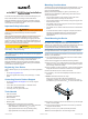


echoMAP
™
40/50 Series Installation
Instructions
To obtain the best performance and to avoid damage to your
boat, install the device according to these instructions.
Read all installation instructions before proceeding with the
installation. If you experience difficulty during the installation,
contact Garmin
®
Product Support.
Important Safety Information
WARNING
See the Important Safety and Product Information guide in the
product box for product warnings and other important
information.
When connecting the power cable, do not remove the in-line
fuse holder. To prevent the possibility of injury or product
damage caused by fire or overheating, the appropriate fuse
must be in place as indicated in the product specifications. In
addition, connecting the power cable without the appropriate
fuse in place voids the product warranty.
CAUTION
Always wear safety goggles, ear protection, and a dust mask
when drilling, cutting, or sanding.
NOTICE
When drilling or cutting, always check what is on the opposite
side of the surface.
To obtain the best performance and to avoid damage to your
boat, install the device according to these instructions.
Read all installation instructions before proceeding with the
installation. If you experience difficulty during the installation,
contact Garmin Product Support.
Registering Your Device
Help us better support you by completing our online registration
today.
• Go to http://my.garmin.com.
• Keep the original sales receipt, or a photocopy, in a safe
place.
Contacting Garmin Product Support
• Go to www.garmin.com/support for in-country support
information.
• In the USA, call 913-397-8200 or 1-800-800-1020.
• In the UK, call 0808 238 0000.
• In Europe, call +44 (0) 870 850 1241.
Tools Needed
• Drill and drill bits
• #2 Phillips screwdriver
• Marine sealant
•
3
/
8
in. wrench or socket
• Masking tape
• Hardware for the swivel mount (not included)
◦ Self-tapping, pan-head wood screws or pan-head bolts,
either size #8 or a diameter of
5
/
32
in. (4 mm)
◦ Appropriate washers and nuts (if selecting bolts)
◦ Appropriate drill bit for drilling the pilot hole
Mounting Considerations
The device can be mounted using the included bracket, or it can
be mounted flush with the dashboard using a flush-mount kit
(may be sold separately).
Before permanently installing any part of your device, you
should plan the installation by determining the location of the
various components.
• The mounting location must provide a clear view of the
screen and access to the keys on the device.
• The mounting location must be sturdy enough to support the
device and the mount.
• The cables must be long enough to connect the components
to each other and to power.
• The cables can be routed under the bail mount or behind the
device.
• To avoid interference with a magnetic compass, the device
should not be installed closer to a compass than the
compass-safe distance value listed in the product
specifications.
Flush Mounting the Device
NOTICE
Be careful when cutting the hole to flush mount the device.
There is only a small amount of clearance between the case and
the mounting holes, and cutting the hole too large could
compromise the stability of the device after it is mounted.
Using a metal pry tool such as a screwdriver can damage the
trim caps and the device. Use a plastic pry tool when possible.
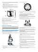
A flush-mount template and hardware can be used to mount the
device in your dashboard.
1
Trim the template and make sure it fits in the location where
you want to mount the device.
2
Secure the template to the selected mounting location.
3
Using a 9.5 mm (
3
/
8
in.) drill bit, drill one or more of the holes
inside the corners of the solid line on the template to prepare
the mounting surface for cutting.
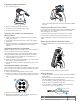
4
Using a jigsaw or rotary cutting tool, cut the mounting surface
along the inside of the solid line indicated on the template.
5
Place the device into the cutout to test the fit.
6
If necessary, use a file and sandpaper to refine the size of
the hole.
7
NOTE: Not all devices have trim caps.
Using a pry tool such as a flat piece of plastic or a
screwdriver, carefully pry up the corners of the trim caps
À
and slide the pry tool to the center
Á
to remove the trim caps.
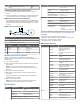
8
Ensure the mounting holes on the device line up with the pilot
holes on the template.
9
If the mounting holes on the device do not line up, mark the
new pilot-hole locations.
10
Using a 3.2 mm (
1
/
8
in.) drill bit, drill the pilot holes.
11
Remove the template from the mounting surface.
December 2014
Printed in Taiwan 190-01834-02_0B