Fishfinder 250/250C high-resolution sonar owner’s manual (Fishfinder 250C shown) 250C Cover.
© Copyright 2004 Garmin Ltd. or its subsidiaries Garmin International, Inc. 1200 East 151st Street, Olathe, KS 66062, U.S.A. Tel. 913/397.8200 or 800/800.1020 Fax 913/397.8282 Garmin (Europe) Ltd. Unit 5, The Quadrangle, Abbey Park Industrial Estate, Romsey SO51 9DL, U.K. Tel. 44/1794.519944 Fax 44/1794.519222 Garmin Corporation No. 68, Jangshu 2nd Road, Shijr, Taipei County, Taiwan Tel. 886/2.2642.9199 Fax 886/2.2642.9099 All Rights Reserved.
Introduction Preface Thank you for choosing the Garmin Fishfinder 250/250C. This product is designed for easy operation and to provide years of reliable service. Operations for the Fishfinder 250 and Fishfinder 250C are the same unless othewise noted. To ensure that you get the most from the Fishfinder 250/250C, please take the time to read this Owner’s Manual and learn the operation of your new unit. This manual is broken down into three sections.
Introduction Warranty and Serial Number Serial Number Use this area to record the serial number (8-digit number located on the back of the unit) in case it is lost, stolen, or needs service. Be sure to keep your original sales receipt in a safe place or attach a photocopy inside the manual. Serial Number: * * , The Fishfinder 250/250C is fastened shut with screws.
Software License Agreement Introduction BY USING THE FISHFINDER 250/250C, YOU AGREE TO BE BOUND BY THE TERMS AND CONDITIONS OF THE FOLLOWING SOFTWARE LICENSE AGREEMENT. PLEASE READ THIS AGREEMENT CAREFULLY. Software License Agreement Garmin grants you a limited license to use the software embedded in this device (the “Software”) in binary executable form in the normal operation of the product. Title, ownership rights and intellectual property rights in and to the Software remain in Garmin.
Introduction Before installing and getting started with your unit, please check to see that your package includes the following items. The package part number can be found on the outside of the box. If any parts are missing, please contact your Garmin dealer immediately.
Transducers The transducer acts as the eyes and ears of your sonar, transmitting sound waves toward the bottom in a cone shape. Proper transducer selection and installation are important to the operation of your unit. It is best to select a transducer that suits the depth of the water that you are on. A wide cone angle transducer works best in shallower water, providing a large coverage or viewing area, but at a decreased bottom resolution.
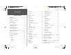
Introduction Table of Contents Introduction . . . . . . . . . . . . . . . . . . . . . . . . . . . i-vi Preface and Registration . . . . . . . . . . . . . . . . . . i Warranty . . . . . . . . . . . . . . . . . . . . . . . . . . . . .ii Software License Agreement . . . . . . . . . . . . . . iii Packing List . . . . . . . . . . . . . . . . . . . . . . . . . . iv Selecting a Transducer . . . . . . . . . . . . . . . . . . . v Table of Contents . . . . . . . . . . . . . . . . . . . . . .
Installing the Fishfinder 250/250C The Fishfinder 250/250C must be properly installed according to the following instructions to get the best possible performance. To complete the installation, you’ll need the appropriate fasteners and tools. Verify that all cables can reach the unit mounting location and also take time to read through these instructions prior to installation. Be sure to always wear safety goggles and a dust mask when drilling, cutting or sanding. When in doubt, seek professional assistance.
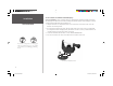
To swivel mount the Fishfinder 250/250C display: Installation Tools (not included) — Drill, Screwdriver (Phillips or Standard), three #8 (4mm) pan head machine bolts with matching nuts and washers and a 5/32” (5mm) drill bit, OR three #8 pan head self-tapping screws and an appropriately-sized drill bit for drilling starter holes. Unit Installation 1. Using the swivel base as a template, mark the location of the three holes that are used to secure the bracket to the mounting surface. 2.
Installing the Unit on the Mounting Bracket 1. Align the slot on the back of the unit with the long mounting knob and slide in place. It may be necessary to adjust the long mounting knob to spread the bracket arms apart. (Turn counter-clockwise to widen the bracket arms, clockwise to tighten.) 2. Adjust the unit angle and tighten the long mounting knob until snug. Installation Unit Installation 3. To tilt the unit, loosen the long mounting knob on the right side of the bracket assembly. 4.
Installation Unit Installation Flush Mounting the Fishfinder 250/250C Unit The Fishfinder 250/250C can be flush mounted on a flat panel. When flush mounting the Fishfinder 250/250C, be sure to choose an appropriately sized location for the unit. Check that all cables reach the unit mounting location before beginning installation. Use the Flush Mount Template provided in the box to determine a location. Always wear safety goggles and a dust mask when drilling, cutting or sanding.
Installation Connecting the Power/Data Cable The power/data cable connects the Fishfinder 250/250C to a 10-35 volt DC system and provides interface capabilities for connecting external devices. The color code in the diagram (pg. 6) indicates the appropriate harness connections. If it is necessary to extend the power/data wires, use a wire of comparable size and keep your extension as short as possible. The unit can be wired directly to your boat’s battery or to an unused holder on your boat’s fuse block.
Installation To Transducer (TX COM 2) DC Positive (RX COM 2) Wiring and Interfacing (red) + 10-35 VDC (RX COM 1) (TX COM 1) (black) - Ground (Power/Data) To Unit You can download a copy of Garmin's proprietary communication protocol document from the Support section of our web site at www.garmin.com. Complete information concerning National Marine Electronics Association (NMEA) format and sentences is available for purchase from NMEA at: NMEA Seven Riggs Avenue Severna Park, MD 21146 U.S.A.
Installing the Transducer Installation Proper transducer installation is key to getting the best performance from your new unit. If the transducer lead is too short, extension cables are available from your Garmin dealer. Coil and secure any excess cable. DO NOT cut the transducer lead or any part of the transducer cable, as this will void your warranty. The cable cannot be spliced and connected to any existing (Garmin or non-Garmin) transducer cables.
Shoot-Thru-Hull Installation Installation Mounting the Transducer To avoid drilling a hole to mount a thru-hull transducer, a transducer may be secured with epoxy inside a boat (“shoot-thru-hull” installation). This type of installation can provide better noise reduction and allow you to use a higher gain setting. For a transducer to be mounted inside the hull (shoot-thru, not thru-hull), the boat must be fiberglass, with no core. Contact your boat manufacturer if you are unsure.
Testing the Installation Installation While it is possible to perform some checks with the boat trailered, the boat should be in the water to properly test the sonar portion of the installation. Press the POWER/BACKLIGHT key (see pg. 10) and the Fishfinder 250/250C should power on. If the unit fails to power on, verify that the wiring adapter is seated properly in the back of the unit, the Red and Black wires are connected to the correct polarity, and that the 2-Amp fuse is installed and not blown.
Unit Operation Using the Keypad The keypad contains the following keys: Keypad Usage ARROW Keys— used to select (highlight) menu options and enter data. Also control movement of the cursor when paused in Pointer mode. Allow direct control of Sonar Page Adjustments. ENTER Key— selects a highlighted menu option. When entering data, allows you to initiate entry and then accept the selected value(s).
Sonar Page The Sonar Page is where your Fishfinder 250/250C becomes a powerful fishfinder/flasher. If the unit does not detect a transducer, a “Sonar Turned Off” message is displayed on the Sonar Page. If in Simulator mode, a “Running Simulator” message is displayed. The currently selected Adjustment option (see pg. 12) is displayed in the top left of the screen. Directly below the Adjustment option, the screen displays numeric data such as Depth, Water Temperature and Water Speed (see pg. 17-18).
Unit Operation Adjustment Menu Options Using the Adjustment Menu The Adjustment Menu allows direct access to the settings and features most commonly used on the Sonar Page. There are 10 main adjustment options available: Range, Zoom, View, Gain, Target Level, Whiteline, Frequency, Depth Line, Noise Reject, and Scroll. All adjustments may be made by using the ARROW keys and ENTER key.
The Zoom function has seven settings: No Zoom –– Displays the sonar picture with no zoom. 2x Split –– Shows two reduced-size sonar pictures at the same time. The right half of the display screen shows the complete sonar picture at its original scale. The left half shows a portion of the original picture at 1/2 depth scale. 2x Zoom –– Displays the 2x zoomed picture on the full screen and does not show the original scale picture.
Unit Operation Adjustment Menu Options You may resize the split line to the left or right. • Whiteline — controls how the unit displays information about the bottom type (hard or soft). With the Whiteline ‘Off’, all high-intensity bottom returns are displayed as red on the Fishfinder 250C and black on the Fishfinder 250. With Whiteline set at ‘Normal’ or 1-100%, this option can be used to better determine bottom hardness. See page 26 for more information on this feature.
Pausing the Sonar Page You may pause the Sonar Page to stop it from scrolling. The paused screen allows you to take a better look at sonar returns. When in this mode, the word “Paused” is displayed at the bottom of the screen and a Pointer cursor is activated. You may move the Pointer around on the paused sonar graph in order to reference sonar items and mark waypoints for that location (if attached to a Garmin GPS or compatible NMEA navigation device. See pg. 5.
Unit Operation Main Menu Options Main Menu The Main Menu contains the unit settings that usually do not require frequent change. The Main Menu is divided into eight tabs: Graph, Tools, Temp, Alarms, System, Units, Sonar and Time. Each tab is described in more detail in this section. To enter the Main Menu, press and hold the ADJ/MENU key. The first time you enter the Main Menu, the ‘Graph’ tab is highlighted in black. Press the UP or DOWN ARROW keys to highlight different tab selections.
• Background Color (Fishfinder 250C only) — allows you to change the background color of the sonar display. Choices are Black, Blue or White. • Number Size — allows you to choose between a Normal or Large sized Basic depth/temp/speed display. This does not change the Advanced data field number sizes. • Temperature and Water Speed — hides or displays temperature and water speed on the Sonar Page. When set to ‘Auto’, the unit automatically displays this information only if it is received from the transducer.
Unit Operation To toggle the data field display: 1. Use the ARROW keys to highlight the ‘Advanced Data Fields’ field and press ENTER. 2. Select ‘On’ or ‘Off’ and press ENTER. Main Menu Options To access the Advanced data setup: 1. Use the ARROW keys to highlight ‘Configure Advanced Data Fields’ and press ENTER. You may either directly edit an existing field on the left or add a new data field from the list on the right.
Alarms Tab Unit Operation Contains settings for the unit’s alarms. (For a list of alarms and unit messages, see page 28.) The Alarms Tab is divided into two submenu tabs: Sonar alarms and System alarms. Sonar alarms: Main Menu Options • Fish — sets alarm/icon to sound/display when unit detects a fish of the specified symbol size. • Shallow Water/Deep Water — set alarms to sound when you enter an area of specified depth that is too shallow and/or too deep.
Unit Operation Main Menu Options Main Menu - System Tab System Tab Controls various system and interface settings. The following settings are available: • Beeper — controls audible beep. Select from ‘Off’, ‘Alarms Only’ (sounds for alarms/messages), or ‘Key and Alarm’ (sounds for key presses and alarms/messages). • Display Mode — select ‘Fishfinder’ to display the scrolling sonar image on the Sonar Page, or select ‘Depth Sounder’ to show only numeric data for Depth, Water Temp, and Water Speed.
• Heading — select the reference used in calculating heading information for the the following Advanced data fields: Bearing, Compass, Course, and Track (see pg. 17-18). ‘True’ will display data with reference to True North. ‘Magnetic’ will display data with reference to Magnetic North using the magnetic variation value received in the RMC NMEA sentence (see pgs. 5-6). Sonar Tab Unit Operation Main Menu Options Allows you to set up initial settings and calibrations.
Unit Operation accurate) or a stopwatch to determine your speed over a certain distance (distance / time = speed). It is recommended that the calibration take place in water having little or no current. To calibrate the water speed: Main Menu Options 1. Use the ARROW keys to highlight ‘Calibrate Water Speed’ and press ENTER. 2. Bring the boat to a cruising speed. Both the top GPS ground speed and uncalibrated water speed will be shown at the bottom of the calibration window.
Understanding Sonar On the Water If you are unfamiliar with basic sonar, or need help determining what is displayed on the graph, this section may be for you. This section is intended to help the novice user gain some understanding of how the Fishfinder 250/250C operates and how it can help improve their fishing productivity. To understand what the unit is displaying, it is important to have a general knowledge of how the unit works and how it determines what to display.
Transducer Coverage On the Water Transducer Coverage The area covered by the transmitted sound waves is determined by the cone angle of the transducer and the water depth. Cone angles may vary between different types of transducers. For example, a 50kHz frequency may provide a “wide” 40° cone angle, with a coverage width that is approximately 2/3 of the water depth.
Understanding the Graph It is important to understand that the unit does not display a 3-D representation of the underwater environment. The unit can display multiple items at the same time, but cannot determine where each return originated – only when it was received. Examples 1 and 2 provide a look at the underwater world from a top view, and illustrate how these views would be displayed on the graph. On both graphs it appears the fish and tree are side by side as shown in Example 1.
On the Water Whiteline and Thermoclines ) Whiteline can also help you to determine the type of bottom structure that is displayed on the graph. By determining the hardness of the structure, you can make a better informed decision on the type of structure. Whiteline The Fishfinder 250/250C can help you to determine if the bottom is hard or soft. When the sonar soundwaves are reflected back by the bottom, a hard bottom returns a stronger signal than a soft bottom.
Physical Specifications Size: 6.1" W x 4.9" H x 2.9" D (15.5 cm x 12.5 cm x 7.4 cm) Weight: 1.1 lbs. (0.5 kg) Display: (Fishfinder 250) 4.5" diagonal (11.4 cm), 3.2” W x 32” H (8.1 cm x 8.1 cm) high-contrast 10-level grayscale FSTN display with adjustable brightness (320 x 320 pixels) (Fishfinder 250C) 4.5" diagonal (11.4 cm), 3.2” W x 3.2” H (8.1 cm x 8.
Appendix B Messages and Alarms The Fishfinder 250/250C uses an on-screen pop-up message system to alert you to unit operating characteristics. Press the ENTER key to acknowledge the message. Battery Alarm — Battery voltage has fallen below the value entered in the Battery Alarm setup. Battery Voltage High— Input voltage too high, unit will shut off. You must lower input voltage. Boat is not Moving Fast Enough to Calibrate — Boat is not moving fast enough for the speed wheel to provide a valid speed.
A Accessories iv-v ADJ/MENU Key 10 Adjustment Menu 12 Adjustment Menu Options 12 Advanced Data Fields 17 Advanced Display 17 Alarms 19, 28 Alarms Tab 19 ARROW Keys 10 Automatic Scroll Speed 21 B Background Color 17 Backlight 10 Basic display 17 Battery Alarm 19 Beeper 20 Bottom Lock 13 Bottom Split 13 C Date 22 Daylight Savings Time 22 Deep Water Alarm 19 Defaults 14, 20 Depth 11-12, 15-17, 20 Depth Line 14 Depth Number 17, 21 Depth Units 20 Display Mode 20 Distance Units 20 Drift Alarm 19 E ENTER Key 10 F
Appendix C Index P Packing List iv Pointer 10, 12, 15 Position Format 20 POWER/BACKLIGHT key 9-10 Power Up 9 Preface i R Range 12 Registration i Reset Odometer 20 Reset Scale 18 S Scale 16 Scroll 14-15 Scroll Speed 21 Serial Number ii Setting an Alarm 19 Shallow Water Alarm 19 Simulator 20 30 250C Manual.
250C Cover.
For the latest free software updates (excluding map data) throughout the life of your Garmin products, visit the Garmin web site at www.garmin.com. © Copyright 2004 Garmin Ltd. or its subsidiaries Garmin International, Inc. 1200 East 151st Street, Olathe, Kansas 66062, U.S.A. Garmin (Europe) Ltd. Unit 5, The Quadrangle, Abbey Park Industrial Estate, Romsey, SO51 9DL, U.K. Garmin Corporation No. 68, Jangshu 2nd Road, Shijr, Taipei County, Taiwan www.garmin.com Part Number 190-00328-00 Rev. A 250C Cover.