Rev A Page All LOG OF REVISIONS Description Complete Supplement FAA Approval Seyed-Joussef Hashemi Manager Flight Test Branch ANM-160L FAA, Los Angeles ACO Transport Airplane Directorate Date: July 15, 2008 AFMS, GARMIN G500/G600 SYSTEM FAA APPROVED 190-00601-01 Rev.
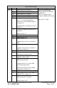
Rev B Page 7 8 11 12 13 14 15 LOG OF REVISIONS Description Added GAD 43 to section 1.2 Added section 1.4 Added GAD 43 to diagram Added GAD 43 to diagram Added section 1.10 Changed GDU s/w to 3.01, AHRS s/w to 2.12, GNS 400W/500W software to 3.20, and added GAD 43 to section 2.2 Added section 2.5 Added section 2.6 Added section 2.10 Added section 2.13 19 Updated section 2.14 to account for SVT Added section 2.17 25 26 Date: July 17, 2009 Updated names of charting services in section 2.
LOG OF REVISIONS Rev C Page 16 Description Added section 2.8. FAA Approval Robert Grove ODA STC Unit Administrator GARMIN International, Inc ODA-240087-CE D 11 12 16 Remove requirement for standby ADI for VFR operations/installations. Add maximum airspeed limitation section. Date: September 15, 2009 Robert Grove ODA STC Unit Administrator GARMIN International, Inc ODA-240087-CE Date: November 17, 2009 AFMS, GARMIN G500/G600 SYSTEM FAA APPROVED 190-00601-01 Rev.
Rev E Page All 7 9 10, 11 13 13 14 16 18 18 19 21 23 23 24 25 LOG OF REVISIONS Description Changed GPS/WAAS to GPS/SBAS. Corrected typographical errors. Updated section 1.1 for new features. Added new feature descriptions to sections 1.7, 1.8, and 1.9. Updated block diagrams for new features. Updated section 2.2 for applicability to this AFMS revision. Removed GPS navigator software table. Updated section 2.3 with limitation on use of helicopter databases and SD card usage with GSR 56 datalink.
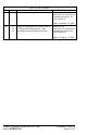
Rev F Page All 10 14 20, 21 25 G All LOG OF REVISIONS Description Changed references to GNS navigators to GPS/SBAS navigators. Inserted new section 1.10 for HSDB interface description. Inserted new section 2.3 for moving map limitations. Moved rate-of-turn failure description from section 3.3.1 to section 3.3.2. Added checkbox for disabled altitude alerter in section 4.4. Re-issue complete supplement. Revised section 2.14 limitation on GPS/SBAS vertical coupling.
Rev H Page All LOG OF REVISIONS Description Re-issue complete supplement. Revised information on system power sources in section 1.2. Revised audio panel description in section 1.6. Updated block diagrams in sections 1.12 and 1.13. Updated System Software Requirements in section 2.2. Revised Moving Map limitation in Section 2.3. Revised SafeTaxi and Airport Directory descriptions in section 2.4. Clarified applicability of section 2.11.
Rev J K Page All All LOG OF REVISIONS Description FAA Approval Re-issue complete supplement. Corrected navigation radio information in Section 1.1. Corrected Auto Slew description in Section 2.11. Updated Bendix/King Altitude Preselect functionality in Section 4.6.6.3. Added G500 content to applicable sections. Added Terrain Alerting and Terminal Procedures to section 1.1. Moved Traffic and Weather Systems to separate sections, 1.7 and 1.8. Updated software versions in section 2.2. Moved sections 2.
TABLE OF CONTENTS SECTION 1. GENERAL ................................................................................. 11 1.1 1.2 1.3 1.4 1.5 1.6 1.7 1.8 1.9 1.10 1.11 1.12 1.13 1.14 G500/G600 PRIMARY FLIGHT / MULTI-FUNCTION DISPLAY SYSTEM . 11 SYSTEM POWER SOURCES .................................................................. 12 NAVIGATION SOURCES ....................................................................... 12 SYNTHETIC VISION TECHNOLOGY (SVT)............................................
SECTION 3. EMERGENCY PROCEDURES .............................................. 27 3.1 3.2 3.3 EMERGENCY PROCEDURES ................................................................. 27 ABNORMAL PROCEDURES ................................................................... 31 WARNINGS, CAUTIONS, AND ADVISORIES ........................................... 34 SECTION 4. NORMAL PROCEDURES ...................................................... 37 4.1 PFD KNOB & PFD SOFT KEYS .....................................
Section 1. GENERAL 1.1 G500/G600 Primary Flight / Multi-Function Display System The G500/G600 System consists of a Primary Flight Display (PFD) and MultiFunction Display (MFD) housed in a single Garmin Display Unit (GDU), plus an Air Data Computer (ADC), Attitude and Heading Reference System (AHRS), and optional signal adapter (GAD).
1.2 System Power Sources The G500/G600 system depends on electrical power to function. The Garmin Display Unit (GDU), Attitude and Heading Reference System (AHRS), and Air Data Computer (ADC) are directly tied to the aircraft’s main or essential bus and energized when the aircraft master switch is turned on. Other systems, like the navigation equipment, weather datalink, autopilot and Adapter (GAD) are typically located on the avionics bus and may not be functional when this bus is powered off.
1.4 Synthetic Vision Technology (SVT) SVT uses an internal terrain database and GPS location to present the pilot with a synthetic view of the terrain in front of the aircraft. The purpose of the SVT system is to assist the pilot in maintaining situational awareness with regard to the terrain and traffic surrounding the aircraft.
Flight Path Marker (FPM); an indication of the current lateral and vertical path of the aircraft. The FPM is always displayed when synthetic terrain is selected for display. Traffic; a display on the PFD indicating the position of other aircraft detected by a traffic system interfaced to the G500/G600 system. Horizon Line; a white line indicating the true horizon is always displayed on the SVT display.
1.6 Audio Panel The G500/G600 system may be interfaced to the aircraft audio panel to provide aural alerting generated by the G500/G600 (required for TAWS-B installations). 1.7 Traffic Display The G500/G600 system can display traffic data from interfaced traffic systems. Sources of traffic data include TIS-A traffic via the Garmin GTX Series Mode-S Transponders, TAS/TCAS traffic from various active traffic awareness systems, and ADS-B traffic from Garmin ADS-B transceivers.
1.11 High Speed Data Bus Interface Some Garmin equipment connected to the G500/G600 system utilizes the High Speed Data Bus (HSDB) interface. HSDB is similar to an Ethernet bus and provides a high-speed interface between Garmin avionics. Like Ethernet, data between two units may be passed through intermediate “hub” units. Interfaced equipment that uses HSDB includes the GTN 6XX/7XX navigators, GDL 69 datalink receiver, GDL 88 ADS-B transceiver, GWX 68/70 weather radar, and GTS 8XX traffic systems.
1.12 Single G500/G600 Operational Block Diagram Equipment Installed per this STC Adapter (optional) GAD 43/43e Aircraft Systems Magnetometer GMU 44 AHRS GRS 77 Electric Standby Attitude*** PFD/MFD Display GDU 620 (optional) Air Data Computer GDC 74() Temperature Probe GTP 59 Audio Panel (optional)** No. 1 GPS/SBAS Navigator (required) Traffic (optional) No. 2 GPS/SBAS Navigator (optional) Datalinks (optional) No. 1 VOR/Localizer/GS (optional) Weather Radar (optional) No.
Copilot PFD/MFD Display GDU 620 Equipment Installed per this STC AFMS, GARMIN G500/G600 SYSTEM FAA APPROVED Magnetic Compass Standby Altimeter (required on pilot side only) Standby Attitude* Standby Airspeed Video Source (optional)** StormScope (optional)** Radar Altimeter (optional) Weather Radar (optional)** Datalinks (optional) Autopilot/Flight Director (optional)** Traffic (optional)** ADF, DME (optional)** No. 2 VOR/Localizer/GS (optional)** No. 1 VOR/Localizer/GS (optional)** No.
1.
Section 2. LIMITATIONS 2.1 Cockpit Reference & Pilot’s Guide The Garmin G500/G600 Cockpit Reference Guide P/N 190-00601-03, Revision G or later appropriate revision must be immediately available to the flight crew. 2.2 System Software Requirements The G500/G600 must utilize the following or later FAA approved software versions for this AFMS revision to be applicable: Component GDU 620 GRS 77 Identification PFD/MFD AHRS Software Version 7.00 3.04 2.
2.8 AHRS Normal Operating Mode The Attitude and Heading Reference System integrity monitoring function requires GPS and Air Data to be provided to the AHRS. Note: Attitude will remain valid if one of these systems becomes inoperative. Flight in IMC is not authorized unless the AHRS is receiving valid GPS and valid Air Data. The G500/G600 monitors these integrity systems automatically and will alert the pilot when the AHRS is not receiving GPS or Air Data.
The system is not capable of automatically setting the inbound VHF NAV course pointer if an approach is not loaded in the GPS/SBAS Navigation System. Auto slewing the VHF NAV course pointer to the correct selected course is a database dependent function. The pilot shall confirm the inbound course pointer is set to the proper course prior to initiating any transition on any VHF NAV approach. 2.
2.15 TAWS Function [GDU 620 Units with internal TAWS] Only the G600 system optionally contains Class B TAWS, a TSO-C151b certified function. The G600 terrain configuration is indicated on the dedicated terrain page of the MAP group. “TAWS-B” will be displayed as the page title if this function is configured. Pilots are authorized to deviate from their current ATC clearance to the extent necessary to comply with TAWS warnings. Navigation shall not be predicated upon the use of TAWS.
2.18 Active Weather RADAR RADAR is broadcasting energy while in Weather or Ground mapping modes. If the G500/G600 system is configured to control an airborne weather radar unit, observe all safety precautions, including: Do not operate in the vicinity of refueling operations. Do not operate while personnel are in the vicinity (approximately 20 feet) of the radar sweep area.
2.20 Kinds of Operations Unless placarded as limited to VFR only operations, G500/G600 equipment installed in a certified aircraft is approved for Day and Night / VFR and IFR operations in accordance with 14 Code of Federal Regulations Part 91, Part 121, and Part 135 when appropriately maintained.
2.23 Electronic Standby Instrument Power The independent power source for the electronic standby instrument(s) shall be verified to be operational before flight, or the electronic standby(s) must be considered inoperative. For the verification procedure, refer to the approved Airplane Flight Manual and/or Instructions for Continued Airworthiness for the independent power source. 2.24 Electronic Flight Bag (EFB) Applications Class 3 EFB applications have not been evaluated as part of this STC.
Section 3. EMERGENCY PROCEDURES 3.1 Emergency Procedures 3.1.1 PFD 1 Failure PFD 1 failure is indicated by the loss of displayed information on the PFD, including blank, frozen, or unresponsive display. 1. 2. Use standby flight instruments for attitude, airspeed, altitude, and heading reference. Refer directly to navigation source for navigation information (such as GPS). If autopilot is engaged: 3. Verify autopilot mode and cross check against standby flight and navigation data. 3.1.
3.1.3 Air Data Computer (ADC) Failure Air Data Computer failure is indicated by a red X and yellow text over the airspeed, altimeter, vertical speed, TAS and OAT displays. Some derived functions, such as true airspeed and wind calculations will also be lost. If valid GPS data is available, the PFD will automatically revert to display GPS calculated altitude relative to mean sea level. This GPS altitude is displayed above the altitude tape. 1. 2.
3.1.6 Loss of Electrical Power to 2-inch Electric Standby Attitude Indicator (flashing or steady amber STBY text) (MidContinent 4200 Series) When a 2-inch electric standby attitude indicator is installed, loss of primary electrical power to the attitude indicator is annunciated by amber STBY text on the Annunciation Control Unit. The attitude indicator is operating on backup battery power, and pilot action may be required for the gyro to continue operating.
3.1.7 TAWS WARNING Red annunciator on PFD and aural “PULL UP”: 1. 2. Disconnect Autopilot. Initiate maximum power climb at best angle of climb airspeed (V X). After warning ceases: 3. 4. Climb and maintain safe altitude. Advise ATC of altitude deviation, if appropriate.
3.2 Abnormal Procedures 3.2.1 Heading Failure Heading failure is indicated by replacement of the digital heading display with amber “HDG” text and a red X. If valid GPS ground track is available, it will automatically be displayed in place of heading. The HSI heading bug and course pointer will continue to function normally, using GPS ground track as a reference instead of magnetic heading. If GPS track is not available: 1. 2. Use standby compass for heading reference.
3.2.2 GPS Data Failure GPS data failure may be indicated by any or all of following: Loss of GPS course deviation information on HSI Amber “LOI” text on the HSI Amber “NO GPS POSITION” text on the MFD moving map Loss of waypoint bearing or distance information 1. Select alternate GPS source, if available, by pressing “1-2” softkey on PFD. If alternate GPS source is not available: 2.
3.2.5 Electrical Load Shedding The following equipment is considered non-essential. If it becomes necessary to reduce electrical load (for example, during loss of generators or alternators), power to these units may be removed in the order listed. 1. PFD 2 circuit breaker(s) [if installed] – PULL 2. AHRS 2 circuit breaker(s) [if installed] – PULL 3. ADC 2 circuit breaker(s) [if installed] – PULL 4. GAD circuit breaker(s) [if installed] – PULL 3.2.
3.3 Warnings, Cautions, and Advisories The following tables show the color and significance of the warning, caution, and advisory messages which may appear on the G500/G600 displays. NOTE The G500/G600 Cockpit Reference Guide and the G500/G600 Pilot’s Guide contain detailed descriptions of the annunciator system and all warnings, cautions and advisories. 3.3.
3.3.2 Caution annunciations – Yellow Annunciation Pilot Action CHECK Fly the aircraft ATTITUDE manually and crosscheck GDU 620 Autopilot will attitude indication automatically with standby attitude disconnect. indicator and other sources of attitude Note: Only information appears with the (airspeed, heading, installation of an altitude, etc.) optional GAD 43 Cause The GDU 620 attitude monitors have detected an AHRS malfunction, or the inability to actively monitor the AHRS output.
TAWS N/A, TAWS FAIL NO DATA Use vigilance, terrain depiction and TAWS alerting is no longer provided. Displayed on dedicated display pages. Indicates that data from the interfaced sensor is not available Database errors or lack of required GPS position. Loss of connection or failure of interfaced sensor. 3.3.3 Advisories – White Annunciation Pilot Action Various Alert View and understand all advisory messages.
Section 4. NORMAL PROCEDURES Refer to the Garmin G500/G600 PFD/MFD System Cockpit Reference Guide P/N 190-00601-03 or G500/G600 Pilot’s Guide P/N 190-00601-02, for normal operating procedures. This includes all Primary Flight Display and MultiFunction Display information. Although intuitive and user friendly, the G500/G600 System requires a reasonable degree of familiarity to avoid becoming too engrossed at the expense of basic instrument flying in IMC and basic see-and-avoid procedures in VMC.
Soft keys at the bottom of the display allow for some quick functions to be performed on each page. The soft keys operate by press and release. More detailed configuration is typically available by pressing the MENU button, which is on the right side of the display. Pressing and holding down the CLR key is a shortcut to get back to the main map page on the MFD. This can be used as a quick way back, or when the pilot has selected a submenu within the system.
4.6 Autopilot Operations with the G500/G600 System The G500/G600 System offers various integration capabilities dependent mainly upon the type of autopilot installed in a particular aircraft. The G500/G600 installation in this aircraft provides the following autopilot integration capabilities (appropriate boxes will be checked): This installation does not interface with the autopilot (basic wing leveling autopilot or no autopilot is installed in the aircraft).
4.6.2 Course / NAV Selection coupling to the autopilot When operating the autopilot in NAV mode, the deviation information from the installed navigation sources (i.e. GPS1, GPS2, NAV1, NAV2) is switched via the G500/G600 PFD display. Whatever is displayed on the HSI is the NAV source the autopilot is following. Most autopilots also use the course datum to determine the best intercept angles when operating in NAV mode. 4.6.
When GPSS is selected on the PFD, GPSS is annunciated in the lower left portion of the PFD. The GPSS mode annunciation depends on the location of the NAV STATUS information, as shown below. NAV STATUS STYLE 1 NAV STATUS STYLE 2 NOTE GPSS mode is selectable from PFD 2, but GPSS is not annunciated on PFD 2. The GPSS commands to the autopilot are based on the GPS source displayed on PFD 1. When GPSS is selected on the PFD, GPSS turn commands are converted into a heading error signal to the autopilot.
4.6.6.2 Collins Autopilots To preselect and capture a selected altitude: 1. Select the desired altitude with the PFD selected altitude bug. 2. Select ALT SEL mode on the autopilot flight control panel. CAUTION Changing the selected altitude bug while ALT SEL mode is selected may result in autopilot mode changes. Verify the autopilot mode after changing the selected altitude. 4.6.6.3 Bendix/King Autopilots To preselect and capture a selected altitude: 1.
4.6.7 Vertical Speed Bug Coupling Certain autopilots may be coupled to the PFD vertical speed bug for maintaining a selected vertical speed. Except as described in this section, refer to the autopilot AFMS and/or Pilot’s Guide for autopilot system operation. 4.6.7.1 S-Tec Autopilots To select and maintain a vertical speed: 1. Select the desired vertical speed with the PFD vertical speed bug. 2. Press VS on the autopilot programmer computer to engage vertical speed mode.
4.6.8 Flight Director Display If autopilot flight director commands are interfaced to the G500/G600, they will be presented as a single cue flight director on the PFD. Control of the flight director is accomplished via the autopilot/flight director controller; there are no pilot controls or adjustments for the flight director on the G500/G600. The G500/G600 system limits the distance the flight director pitch commands may deviate from the aircraft attitude icon.
4.6.9 GAD 43 Operation The GAD 43 Adapter may provide attitude, heading, and barometric correction information from the G500/G600 System to the autopilot. The GAD 43 can also be configured to provide synchro heading output to other systems and its attitude output can be used for RADAR stabilization. The GAD 43 has the ability to disconnect the autopilot if an error in the GAD 43 output or GRS 77 is detected. This disconnect mechanism must be tested prior to each flight in the following manner: 1. 2. 3.
Section 5. PERFORMANCE No change. Section 6. WEIGHT AND BALANCE See current weight and balance data. AFMS, GARMIN G500/G600 SYSTEM FAA APPROVED 190-00601-01 Rev.
Section 7. SYSTEM DESCRIPTIONS Garmin also provides a detailed G500/G600 Pilot’s Guide P/N 190-00601-02. This reference material is not required to be on board the aircraft but does contain a more in depth description of all the functions and capabilities of the G500/G600. 7.1 Databases The G500/G600 utilizes several databases. Database titles display in yellow if expired or in question (Note: the G500/G600 receives the calendar date from the GPS, but only after acquiring a position fix).
The airport directory database contains information on landing facilities, such as operating hours, services available, and transportation/lodging resources. Airport directory information may be available from multiple sources and coverage areas. This database is updated on a 56-day cycle. 7.2 Electric Standby Attitude Gyro If an electric standby attitude gyro is installed, the gyro operates from the aircraft electrical system with a dedicated emergency battery specific to the electric gyro.
7.4 TAWS Function [GDU 620 Units with internal TAWS] In Dual G600 installations, TAWS audio is only provided by the Pilot side GDU. If the Pilot side GDU TAWS becomes inoperative, the Co-Pilot side GDU TAWS visual annunciations may still function, but the aural TAWS alerts will not be heard. 7.
7.7 ADS-B Traffic System Interface The G500/G600 system can be interfaced to sources of ADS-B traffic. The nose of the ownship symbol on both the G500/G600 main map page and dedicated traffic page serves as the actual location of your aircraft. The center of the traffic target icon serves as the reported location for the target aircraft. Motion vectors for traffic may be displayed in either absolute or relative motion.
7.10 Depiction of Obstacles and Wires 7.10.1 Dedicated Terrain Page The dedicated Terrain page will always depict point obstacles at zoom scales of 10 nm or less and depict wire obstacles at zoom scales of 5 nm or less. The obstacle or wire overlay icon, shown below, will be shown near the bottom of the display when the obstacle or wire depiction is active based on the zoom scale.