G500/600 Cockpit Reference Guide
© 2008-2015 Garmin Ltd. or its subsidiaries. All rights reserved. This manual reflects the operation of system software version 7.00, or later. Some differences in operation may be observed when comparing the information in this manual to later software versions. Garmin International, Inc., 1200 East 151st Street, Olathe, KS 66062, U.S.A. Tel: 913.397.8200 Fax: 913.397.8282 Garmin AT, Inc., 2345 Turner Road SE, Salem, OR 97302, U.S.A. Tel: 503.391.3411 Fax 503.364.2138 Garmin (Europe) Ltd.
AVIATION LIMITED WARRANTY All Garmin avionics products are warranted to be free from defects in materials or workmanship for: two years from the date of purchase for new Remote-Mount and Panel-Mount products; one year from the date of purchase for new portable products and any purchased newly-overhauled products; six months for newly-overhauled products exchanged through a Garmin Authorized Service Center; and 90 days for factory repaired or newly-overhauled products exchanged at Garmin in lieu of repair.
WARNINGS, CAUTIONS, AND NOTES Warnings, Cautions, & Notes WARNINGS, CAUTIONS, AND NOTES ii WARNING: Navigation and terrain separation must NOT be predicated upon the use of the terrain function. The GDU 620 Terrain Proximity feature is NOT intended to be used as a primary reference for terrain avoidance and does not relieve the pilot from the responsibility of being aware of surroundings during flight.
WARNINGS, CAUTIONS, AND NOTES WARNING: Do not use basemap (land and water data) information for primary navigation. Basemap data is intended only to supplement other approved navigation data sources and should be considered as an aid to enhance situational awareness. WARNING: Traffic information shown on the GDU 620 Multi-Function Display is provided as an aid in visually acquiring traffic.
WARNINGS, CAUTIONS, AND NOTES WARNING: Do not use Terrain-SVT information for primary terrain avoidance. Terrain-SVT is intended only to enhance situational awareness. WARNINGS, CAUTIONS, AND NOTES CAUTION: The United States government operates the Global Positioning System and is solely responsible for its accuracy and maintenance. The GPS system is subject to changes which could affect the accuracy and performance of all GPS equipment.
WARNINGS, CAUTIONS, AND NOTES NOTE: This device complies with part 15 of the FCC Rules. Operation is subject to the following two conditions: (1) this device may not cause harmful interference, and (2) this device must accept any interference received, including interference that may cause undesired operation. NOTE: Terrain data is not displayed when the aircraft latitude is greater than 75° North or 60° South.
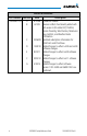
Record of Revisions Part Number Revision 190-00601-03 A B C D E F G vi Date 6/12/08 6/1/09 Description Production release Revision reflects functionality added with SW version 3.00. Added SVT, TAWS-B, Terrain Proximity, Wind Vectors, Minimums Bug, GAD 43, and Weather Radar information. 10/26/09 Updated subscription information for FliteCharts and ChartView. 11/30/10 Added changes to reflect v4.00 and v5.00 software changes. 8/23/11 Added changes to reflect v6.00 software changes.
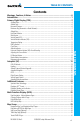
TABLE OF CONTENTS Contents Warnings, Cautions, & Notes............................................................................. ii Introduction....................................................................................................... 1 Primary Flight Display (PFD).............................................................................. 2 Autopilot (AP).................................................................................................. 19 GAD 43 Attitude.................
TABLE OF CONTENTS Terrain Pop-Up Alerts...................................................................................................................................43 WX Group........................................................................................................ 44 XM Weather Map Pages..............................................................................................................................44 Customizing the Weather Map..............................................
PRIMARY FLIGHT DISPLAY (PFD) Introduction PFD/MFD NOTE: In some models or installations, the PFD and MFD and their controls are switched to the other side. 190-00601-03 Rev G G500/600 Cockpit Reference Guide 1 PRIMARY FLIGHT DISPLAY This reference guide covers the operation of the GDU 620 as integrated in the G500 and G600 Avionics Display Systems.
PRIMARY FLIGHT DISPLAY (PFD) Primary Flight Display (PFD) 21 1 20 19 18 17 PRIMARY FLIGHT DISPLAY 2 16 3 4 15 5 14 6 7 13 8 9 10 22 11 12 Primary Flight Display (PFD) 1 Airspeed Tape: Displays Groundspeed (GS), Airspeed Trend, Current Airspeed, and True Airspeed (TAS). Markings dependent upon installation configuration. 2 Wind Vector: Displays direction and speed of wind. 3 Heading Select Key: Press HDG and turn PFD knob to set heading bug.
PRIMARY FLIGHT DISPLAY (PFD) Outside Air Temperature (SAT, TAT, or ISA): Displays the current outside air temperature. 9 NAV Status Window: (NAV Style 2 Shown) Displays which GPS is selected as the Active Source, Active Waypoint (WPT), and Distance to Waypoint (DIS). NAV Style 1 (Not Shown) displays Active Source, WPT, DIS, Desired Track (DTK), and Current Track (TRK) at top of screen. 10 PFD Knob: Turn PFD knob to change bug settings, Heading Bug, Course, Altitude Bug, V/S Bug, and Barometer setting.
PRIMARY FLIGHT DISPLAY (PFD) Airspeed Tape The upper left portion of the PFD display provides Groundspeed, Airspeed Trend, Current Airspeed, and True Airspeed information. Current Airspeed is normally shown in white on the black pointer. The Trend Indicator (magenta line) indicates what the airspeed will be in six seconds, if the current acceleration is maintained. If the current acceleration will cause the airspeed to exceed Vne in six seconds, the airspeed is displayed in yellow.
PRIMARY FLIGHT DISPLAY (PFD) V-speeds (Glide, Vr, VX, and VY) default values are set during the installation process, but can be changed and turned on/off from the System Setup page on the first page of the Aux page group. When active (on), the V-speeds are displayed at their respective locations to the right of the airspeed scale.
PRIMARY FLIGHT DISPLAY (PFD) Altitude Tape The upper right portion of the PFD displays the Altitude Bug setting, Current Altitude, Altitude Trend, Altitude Minimums Bug, and the current BARO Setting. The Altitude Trend indicates what the altitude will be in six seconds if the current vertical speed is maintained.
PRIMARY FLIGHT DISPLAY (PFD) Minimums Bug (Barometric or Radar Altimeter) Bug and text are cyan within 2500 ft Bug and text are white within 100 ft Bug and text are yellow when altitude reached Minimums Bug Minimums Box Minimums Annunciations using BARO for Source Alerting is inhibited while the aircraft is on the ground and also, if a value has been set for altitude alerting, until the aircraft reaches 150 feet above the setting for the alert.
PRIMARY FLIGHT DISPLAY (PFD) To set the altitude for the Minimums Bug: PRIMARY FLIGHT DISPLAY 1) While viewing the Active Flight Plan page of the FPL Group, press the small MFD knob to activate the cursor and turn the large MFD knob to the Source selection. 2) Turn the small MFD knob to select Off, BARO, or RAD ALT. 3) Turn the large MFD knob to the ALTITUDE portion of the MINIMUMS section. 4) Turn the small MFD knob to enter the desired altitude. Press the ENT key to confirm selection.
PRIMARY FLIGHT DISPLAY (PFD) Altitude Bug The Altitude Bug is displayed on the Altitude Tape at the selected altitude bug setting. A portion of the Altitude Bug will be displayed at the top or bottom of the altitude tape if the selected altitude bug is off of the tape. Altitude Bug Setting Altitude Bug The Altitude Bug provides visual and aural altitude alerting. Aural alerting occurs within 200 feet (or 1000 feet, as configured) of the Altitude Bug setting or when deviating beyond 200 feet of the bug.
PRIMARY FLIGHT DISPLAY (PFD) Wind Vectors The PFD will display a Wind Vector Field to the left of the HSI when configured by the user. There are four different styles of wind vector displays available. Refer to the System Setup page in the AUX Group section of this guide for instructions on selecting wind vector style. Wind Vectors can only be calculated when the aircraft is in the air.
PRIMARY FLIGHT DISPLAY (PFD) Vertical Deviation Indicator (VDI) The Vertical Deviation Indicator is displayed for ILS and GPS approaches with vertical guidance. The GPS approach glidepath is shown in magenta (G and indicator), while the ILS approach glideslope is shown in green (G and indicator.) Vertical Deviation Source Vertical Deviation Indicator ILS Approach Temperature Display The outside air temperature is displayed to the left of the HSI.
PRIMARY FLIGHT DISPLAY (PFD) DME Indication DME information is displayed in a window in the lower left corner of the PFD. The distance to the station and the NAV source used are shown. DME Information Selected DME DME Hold Annunciation Set Hold for Selected DME DME Indication PRIMARY FLIGHT DISPLAY Clock/Timer The Clock/Timer function displays a clock or timer window in the lower left corner of the PFD.
PRIMARY FLIGHT DISPLAY (PFD) Roll Pointer pointing towards the sky. Roll Scale Zero Pointer Roll Pointer Roll Scale Attitude Indicator with a Sky Pointer Configuration in a Left Turn Roll Scale Zero Roll Pointer Slip/Skid Indicator Slip/Skid Indicator Horizontal Situation Indicator (HSI): Aircraft Heading The top of the HSI displays current heading, current GPS track (magenta diamond), heading trend, and turn rate markings. The heading trend indicates the rate of turn.
PRIMARY FLIGHT DISPLAY (PFD) Current Heading Current GPS Track Turn Rate Markings Heading Trend HSI Heading Markings PRIMARY FLIGHT DISPLAY NOTE: If magnetic heading is lost, GPS ground track will be displayed in place of heading. Adjusting the Course Pointer Press the CRS key and turn the PFD knob to select a course for a VOR/ILS or OBS mode course. HSI Bearing Pointers NOTE: The Bearing Pointer for navigation source 1 (BRG1) will be an arrow with a single line.
PRIMARY FLIGHT DISPLAY (PFD) BRG1 Pointer BRG2 Pointer Selected source for BRG 2 bearing pointer Bearing Pointers on the HSI GPS1 GPS2 VOR1 VOR2 LOC1 LOC2 CDI Source GPS Mode GPS Advisory LOI Suspend MSG LOI OCN ENR TERM APR LNAV LNAV+V LNAV/VNAV LPV LP LP +V 1.00nm 0.
PRIMARY FLIGHT DISPLAY (PFD) CDI Source The CDI Source on the HSI will display which navigation source is selected. Navigation sources available: GPS1, VOR1, or LOC1. Navigation sources available: GPS2, VOR2, or LOC2, if a second source is available. GPS Mode The GPS Mode annunciation on the HSI indicates the current CDI scaling of the GPS navigator. See the GPS navigator pilot’s guide for a description of each mode.
PRIMARY FLIGHT DISPLAY (PFD) Miscompare Annunciations For complete description and conditions of miscompare annunciations, see the G500/600 Pilot’s Guide, P/N 190-00601-02.
PRIMARY FLIGHT DISPLAY (PFD) PRIMARY FLIGHT DISPLAY Switching Between Navigation Sources GPS NAVIGATOR 1 VLOC NAVIGATOR 1 GPS NAVIGATOR 2 VLOC NAVIGATOR 2 CDI Sources The Course Deviation Indicator (CDI) can display two sources of navigation: GPS or NAV (VOR or LOC). Press the CDI soft key to toggle between the available CDI modes, (GPS or VOR). If a second GPS source or NAV source is available, pressing the 1 - 2 soft key will toggle the navigation sources (VOR1 and VOR2, or GPS1 and GPS2).
PRIMARY FLIGHT DISPLAY (PFD) Autopilot (AP) The G500/600 is able to interface to certain autopilot systems to provide the functions described in this section. Please refer to your particular Airplane Flight Manual and autopilot documentation for specific information and operating instructions.
PRIMARY FLIGHT DISPLAY (PFD) Heading PRIMARY FLIGHT DISPLAY The GDU 620 heading bug may be used in conjunction with the “Heading” mode of supported autopilots. When the autopilot is in “heading” mode and the heading bug is adjusted in the normal manner, and the autopilot will turn to and maintain the selected heading. Refer to the Airplane Flight Manual and autopilot system documentation for instructions on how to use the autopilot heading mode.
PRIMARY FLIGHT DISPLAY (PFD) GPSS The GDU 620 will send the GPSS commands from the displayed GPS source to the autopilot. For example, if GPS 1 is displayed on the HSI, the GPSS commands from GPS 1 will be sent to the autopilot. Refer to the Airplane Flight Manual and autopilot system documentation for instructions on how to use the autopilot’s GPSS function. NOTE: GPSS commands are not sent to the autopilot when a VLOC source is displayed on the HSI.
PRIMARY FLIGHT DISPLAY (PFD) Flight Director Display PRIMARY FLIGHT DISPLAY Flight director commands are presented as a single cue flight director on the PFD. SVT Off SVT On Flight Director Bars Showing Aircraft Pitch Vertical Speed Control The GDU 620 vertical speed bug may be used to control vertical speed with certain autopilots. Refer to the Airplane Flight Manual and autopilot system documentation for instructions on how to use the vertical speed mode, if available.
PRIMARY FLIGHT DISPLAY (PFD) Autopilot Mode Annunciations Some autopilots support mode annunciations located at the top of the PFD. Refer to the Airplane Flight Manual and autopilot system documentation for details on the autopilot mode annunciations. When autopilot annunciations are displayed at the top of the PFD, the Nav Status information will be located to the left of the HSI (NAV STATUS Style 2).
PRIMARY FLIGHT DISPLAY (PFD) Additional Features Synthetic Vision Technology™ Synthetic Vision Technology (SVT) is offered as a feature to the G500/600. SVT is primarily comprised of a computer-generated forward-looking, attitude aligned view of the topography immediately in front of the aircraft from the pilot’s perspective. SVT information is shown on the PFD. SVT offers a three-dimensional view of terrain and obstacles.
PRIMARY FLIGHT DISPLAY (PFD) The following features are part of the Synthetic Vision Technology. For more details refer to the G500/600 Pilot’s Guide, Rev. G or later. • Flight Path Marker • Horizon Heading Marks • Terrain/Obstacle Display and Alerting • Three-dimensional Traffic • Wind Vectors • Airport Signs • Runway Display • Water • Zero-Pitch Line • Altitude Minimums Bug NOTE: SVT may be deactivated under certain conditions, such as loss of heading.
MULTI-FUNCTION DISPLAY (MFD) Multi-Function Display (MFD) MULTI-FUNCTION DISPLAY 7 6 5 4 2 1 3 Multi-Function Display (MFD) NOTE: In some models or installations, the PFD and MFD and their controls are switched to the other side. 1 Soft Keys 2 Large MFD knob: Use to move between page groups. 3 Small MFD knob: Use to move within page groups. 4 Enter: Validates or confirms a menu selection or data entry. 5 Clear: Erases information, cancels entries, or removes page menus.
MULTI-FUNCTION DISPLAY (MFD) Page Navigation - Moving Between Pages Page Group Turn Large MFD knob Page Turn Small MFD knob 1) Turn the large MFD knob to move between page groups. 2) Turn the small MFD knob to change pages within the page group. NOTE: Page Group and Page are shown at the bottom of the MFD. 1) Press the MENU key and make the necessary adjustments with the large MFD knob and small MFD knobs. 2) Press the small MFD knob to activate editing.
MULTI-FUNCTION DISPLAY (MFD) MFD Soft Key Map The soft keys available depend on the page displayed and the features available. The soft key “Alerts” is present on the far right position on all MFD pages.
MAP GROUP Map Group Navigation Map 1 and Navigation Map 2 Pages Soft Keys Found on Navigation Map Pages NOTE: Panning can be used in Terrain pages to view elevation levels. 1) While viewing Navigation Map 1 or Navigation Map 2 of the Map Page Group, press the small MFD knob. A flashing arrow (map pointer) will appear in the center of the map page. 2) Turn the large MFD knob to move the map pointer left and right (horizontally).
MAP GROUP Decluttering (DCLTR) the Map Pages MAP GROUP: SETUP OPTIONS There are four levels of decluttering, DCLTR, DCLTR-1, DCLTR-2, and DCLTR-3. DCLTR shows the most detail while DCLTR-3 removes most detail. While viewing Navigation Map 1 or Navigation Map 2 page of the Map Page Group, press the DCLTR soft key. Each successive press of the DCLTR soft key will toggle through the declutter levels.
MAP GROUP Customizing Maps 1) While viewing Navigation Map 1 or Navigation Map 2 of the Map Page Group, press the MENU key. MAP GROUP: SETUP OPTIONS Map Setup Option Menu 2) Press the ENT key to enter the setup page. The selected group will be flashing. 3) Turn the small MFD knob to activate the drop down menu and to move within available groups (Map, Weather, Traffic, or Aviation). Available Groups 4) Press the ENT key to select the group and set your preferences.
MAP GROUP MAP GROUP: SETUP OPTIONS Map Setup Options Group MAP Selections • Orientation (North Up, Track Up, DTK up, HDG up) • North Up At (Off to 500 NM) • Auto Zoom (On or Off) • Land Data (On or Off) • Track Vector Length (Off to 20 mins) • Wind Vector (On or Off) • Enhanced Range Ring (On or Off) • Topo Data (On or Off) • Topo Scale (On or Off) • TERRAIN Data (On or Off) • Obstacle Viewing Range (Off to 15 NM) • Power Line Viewing Range (Off to 15 NM) • Lat/Lon Viewing Range (Off to 500 NM) • Selec
MAP GROUP NOTE: Do not use SafeTaxi or ChartView functions as a basis for ground maneuvering. SafeTaxi and ChartView functions have not been qualified to be used as an Airport Moving Map Display (AMMD). SafeTaxi and ChartView are intended to improve pilot situational awareness during ground operations and should only be used by the flight crew to orient themselves on the airport surface.
MAP GROUP Split Screen Page (Optional) Soft Keys Found on Split Screen Page MAP GROUP: SPLIT SCREEN PAGE External Video is an optional function that displays video provided by an externally mounted video source on the aircraft. 1) While viewing the Map function, turn the small MFD knob to the third page of the map group.
MAP GROUP Traffic Map Page (Optional) Soft Keys Found on Traffic Map Page OPERATE STANDBY MOTION ALT MODE DESELECT STANDBY ABSOLUTE RELATIVE OFF DURATION BACK BELOW NORMAL ABOVE UNRSTD Traffic Display When a traffic alert is generated by an interfaced traffic system, the PFD will display a traffic annunciator and the MFD will have a pop-up screen displaying the detected traffic, if not viewing the Traffic page. To remove the pop-up, press the CLR key.
MAP GROUP Displaying and Operating Traffic Advisory Systems (TAS) Operating Mode Range Ring Non-Threat Traffic Traffic Advisory, Off Scale Aircraft is Out of Range, 1200 ft Above and Climbing MAP GROUP: TRAFFIC PAGE Ownship Symbol Proximity Advisory, Aircraft is 5000 ft Above and Descending Traffic Advisory, 1200 ft Above and Climbing Non-Bearing Traffic (System is Unable to Determine Bearing), Aircraft Distance is 8.
MAP GROUP Press the ALT MODE soft key to change what traffic is displayed. Pressing the BELOW, NORMAL, ABOVE or UNRSTD soft keys will determine what traffic is displayed. The selection is shown in the altitude mode field. The values below define what each altitude mode displays, relative to the altitude of the aircraft.
MAP GROUP MAP GROUP: TRAFFIC PAGE TIS Traffic The Traffic Map Page is configured to show surrounding TIS traffic data in relation to the aircraft’s current position and altitude, without clutter from the basemap. Aircraft orientation on this map is always heading up unless there is no valid heading. TIS receives traffic information from ground stations, and is updated every five seconds. The GDU 620 displays up to eight traffic targets within a 7.
MAP GROUP ADS-B Traffic (Optional) The ADS-B traffic page provides an enhanced display of traffic from a compatible ADS-B In system. Available ADS-B traffic features may include individual target selection and other details, such as type, direction, groundspeed, and motion.
MAP GROUP ADS-B Target Selection Traffic targets displayed on the dedicated traffic page may be selected in order to obtain additional information about a traffic target. 1) Press the small MFD knob to start target selection. 2) Turn the small or large MFD knobs to step through selection of the available targets. MAP GROUP: TRAFFIC PAGE 3) Press the small MFD knob to stop target selection. Press the DESELECT key to stop selection and/or clear target selection.
MAP GROUP Terrain/TAWS-B Page (Optional) Soft Keys Found on Terrain/TAWS-B Page 360 ARC INHIBIT Garmin provides the following Terrain/TAWS selections, based upon your system configuration. WARNING: Do not use Terrain-SVT information for primary terrain avoidance. Terrain-SVT is intended only to enhance situational awareness. NOTE: Terrain data is not displayed when the aircraft latitude is greater than 75° North or 60° South.
MAP GROUP MAP GROUP: TERRAIN/TAWS-B PAGE Class B TAWS FLTA functionality, including visual alerting and aural alerting. Terrain-SVT is provided with the Synthetic Vision functionality and not marketed separately. Garmin Terrain-SVT is available in GDU 620 v3.00 or later, with SVT enabled. • TAWS-B - is an optional feature developed that meets the terrain alerting and ground proximity requirements for Class B TAWS system as defined in TSO-C151b.
MAP GROUP Terrain Pop-Up Alerts TAWS-B Pop-Up Alert on MFD TERRAIN-SVT™ Pop-Up Alert TERRAIN-SVT alerts typically employ a CAUTION or a WARNING alert severity level, or both. When an alert is issued, visual annunciations are displayed and aural alerts are simultaneously issued. Refer to the Alerts section of this guide for more information on alerts, both visual and aural. When an alert is issued, annunciations appear on the PFD and MFD (TAWS page only).
WX GROUP WX Group WX GROUP: XM WEATHER PAGES XM Weather Map Pages Soft Keys Found on XM Weather Map Pages LEGEND FCST TIME WX Alt Dn WX Alt Up NOTE: The preferences set on XM Weather Map pages are unique to each page. Customizing the Weather Map 1) While viewing any of the XM Weather Map pages in the WX Page Group, press the MENU key to display the page menu. Press ENT. 2) Turn the small MFD knob to select Weather Setup 1 or Weather Setup 2 and press ENT.
WX GROUP XM Weather Items WX Page Menu - Weather Setup Adjustment Map Orientation NEXRAD Data Viewing Range NEXRAD Legend Source Echo Top Data Viewing Range Cloud Top Data Viewing Range Lightning Data Viewing Range Cell Mov Data Viewing Range SIG/AIR Viewing Range PIREPS Data Viewing Range METAR Data Viewing Range Surface Data Viewing Range Frz Lvl Data Viewing Range Wnds Aloft Data Viewing Range County Data Viewing Range TFR Data Viewing Range AIREPS Data Viewing rnage Icing Data Viewing Range Turbulence
WX GROUP WX GROUP: XM WEATHER PAGES Weather Legend A mini-legend can be displayed on the XM Weather Map page upper right hand corner for the weather products you selected in the setup menu. To view a full page legend: 1) While viewing any of XM Weather Map pages in the WX Page Group, press the LEGEND soft key. 2) Turn the small MFD knob or large MFD knob to view the entire legend. 3) Exit and return to the map page by pressing either the LEGEND soft key, ENT key, or the small MFD knob.
WX GROUP Garmin Flight Data Services (GFDS) Map Pages Requesting Garmin Flight Data Services (GFDS) Prior to requesting GFDS information, an access code and system ID will need to be assigned. For more information on GFDS and how to register, see the latest revision of the G500/600 Pilot’s Guide, P/N 190-00601-02. After registering you are able to display GFDS data: 1) While viewing any one of the three pages of the WX Group, press the MENU button.
WX GROUP Coverage Area Distances: Remaining FPL, Next 50 NM Next 500 NM Coverage Area Width of Coverage: 50 NM - 500 NM WX GROUP: GFDS PAGES Update Rate: Off - 60 Minutes Cancel Manual Request Manual Request Status of Request GFDS Data Request Page Configuring GFDS Data Request Page 1) Turn the large MFD knob to the Coverage box. Press ENT to select or deselect the coverage areas. Selected coverage areas are denoted by a green check mark.
WX GROUP FIS-B Weather Map Pages LEGEND FCST TIME WX Alt Dn WX Alt Up NOTE: The preferences set on FIS-B Weather Map pages are unique to each page. Customizing the Weather Map 1) While viewing any of the FIS-B Weather Map pages in the FIS-B Page Group, press the MENU key to display the page menu. 2) Turn the small MFD knob to select Weather Setup and press ENT. 3) Turn the large MFD knob to select the desired item to change.
WX GROUP FIS-B Weather Items WX GROUP: FIS-B WEATHER PAGES WX Page Menu - Weather Setup 50 Menu Item Adjustment Map Orientation NEXRAD Data Viewing Range NEXRAD Legend Source SIG/AIR Viewing Range PIREPS Data Viewing Range METAR Data Viewing Range Wnds Aloft Data Viewing Range TFR Data Viewing Range North Up, Track Up Off, 10 NM to 500 NM On/Off CONUS, Regional, Combined Off, 10 NM to 500 NM Off, 10 NM to 500 NM Off, 10 NM to 500 NM Off, 10 NM to 500 NM Off, 10 NM to 500 NM G500/600 Cockpit Referenc
WX GROUP Weather Radar (Optional) Weather Radar Map Page Soft Keys Found on Weather Radar Map Page Operating Mode Weather Alert (GWX only) Control Window Precipitation Scale Weather Radar 190-00601-03 Rev F G600 Cockpit Reference Guide 51 WX GROUP: WEATHER RADAR Operating Mode
WX GROUP Airborne Color Weather Radar WX GROUP: WEATHER RADAR WARNING: Begin transmitting only when it is safe to do so. If transmitting on the ground is necessary, ensure that no personnel or objects are within the minimum safe distance from the radar antenna. For Garmin GWX radars, the minimum safe distance may be up to 14 feet. For 3rd-party radars, refer to the radar pilot’s guide or other manufacturer documentation to determine the minimum safe dis-tance.
WX GROUP Adjusting the Antenna Bearing 1) Press the small MFD knob and turn the large MFD knob to move to the BEARING field. 2) Adjust the azimuth position of the antenna right or left. Monitor the displayed bearing value in the BEARING field. The range of the bearing is R45° to L45°. 1) Press the CONTROL soft key. 2) Press the BRG soft key. Sector Scan (GWX Radars Only) 1) Press the small MFD knob and turn the large MFD knob to move to the SECTOR SCAN field.
WX GROUP Antenna Stabilization 1) To activate or deactivate the antenna stabilization, press the CONTROL soft key. WX GROUP: WEATHER RADAR 2) Press the STAB ON soft key to activate antenna stabilization or press the STAB OFF soft key to deactivate. The current stabilization condition is shown in the upper right of the weather radar display.
AUX GROUP Aux Group External Video Page (Optional) Soft Key Found on External Video Page 1) While viewing the External Video Page of the Aux Page Group, press the desired video soft key (VIDEO 1, VIDEO 2, or FULL). 2) Press the SETUP soft key. The BRIGHTNESS in the CURRENT box will flash. Turn the small MFD knob to change the brightness of the video output. 3) Turn the large MFD knob to CONTRAST and turn the small MFD knob to change the contrast level of the video output.
AUX GROUP System Setup Page Soft Keys Found on System Setup Page AUX GROUP: SYSTEM SETUP PAGE Setting Brightness and Mode 1) While viewing the System Setup Page of the Aux Page Group, press the small MFD knob. The LEVEL in the DISPLAY BRIGHTNESS box will flash. 2) Turn the small MFD knob to brighten or dim the display. 3) Press ENT when you reach the desired level. NOTE: When LEVEL is changed, the MODE defaults to MANUAL.
AUX GROUP Selecting Wind Vector Styles 1) While viewing the System Setup Page of the Aux Page Group, press the small MFD knob and turn the large MFD knob to move to the field in the PFD OPTIONS box. 2) Turn the small MFD knob to select the styles available for displaying wind vectors. Each style shows direction and velocity of the wind. Style 2 Style 3 Style 4 Style 1 Displays headwind and crosswind components Style 2 Displays total wind direction and speed.
AUX GROUP Selecting Temperature Reference 1) While viewing the System Setup page of the AUX page group, press the small MFD knob to activate the cursor. Turn the large MFD knob to highlight the desired Temp Reference value. AUX GROUP: SYSTEM SETUP PAGE 2) Turn the small MFD knob to select the Temp Reference type and press ENT.
AUX GROUP Setting Time Format 1) While viewing the System Setup Page of the Aux Page Group, press the small MFD knob. Turn the large MFD knob to the desired field in the DATE/TIME box. The only items that are able to be modified is the TIME FORMAT and TIME OFFSET. The date and time are coordinated with the GPS. 2) Turn the small MFD knob to display your choices of LOCAL 12hr, LOCAL 24hr, and UTC (Universal Time, Coordinated).
AUX GROUP AUX GROUP: SYSTEM SETUP PAGE MFD Display Units NOTE: At any time during the setting of your preferences, pressing the DFLT UNIT soft key will restore the settings for brightness, synchronization, time format, time offset and display units to the initial settings. NOTE: The corresponding GPS navigator must also be set to match the selection chosen (distance, speed, NAV angle, pressure, and temperature units) on the GDU 620.
AUX GROUP 2) Turn the small MFD knob to display your choices of INCHES(in) or HECTOPASCALS (hpa) for your barometric pressure units. Press ENT to confirm your selection and move to the next preference or press the small MFD knob to exit editing mode. Setting Temperature Units 1) While viewing the System Setup Page of the Aux Page Group, press the small MFD knob and turn the large MFD knob to move to the desired field of the SYSTEM DISPLAY UNITS box.
AUX GROUP XM® Information Page (Optional) Soft Key Found on XM Information Page AUX GROUP: XM RADIO PAGE While viewing the Aux Group, turn the small MFD knob to display the XM Information screen. This page contains the Data Radio and Audio Radio IDs. The only option on this page is to LOCK in your information once your subscription has been activated.
AUX GROUP XM® Radio Page (Optional) Soft Keys Found on XM Radio Page TO 1) While viewing the XM Radio page of the Aux Page Group, press the small MFD knob and then turn the small MFD knob to highlight the desired channel. 2) Press ENT to make the highlighted channel the Active Channel. 3) Press the small MFD knob to end editing. 4) Press CHNL and then the CH+ or CH- soft keys to increment up or down one channel at a time in the active category.
AUX GROUP Volume While viewing the XM Radio page of the Aux Group, press the VOL soft key. Press the VOL+ or VOL- soft keys or turn the small MFD knob to increase or decrease radio volume. Press the small MFD knob when done adjusting. To mute the radio, press the MUTE soft key. To restore the radio volume, press MUTE again or the VOL+ or VOL- soft keys. AUX GROUP: XM RADIO PAGE Storing a Preset Channel While viewing the XM Radio page, you may set a preset for the Active Channel.
AUX GROUP Position Reporting Page Soft Key Found on Position Reporting Page Position Reporting Status The Status window shows the time until the next data transmission and the status of the reporting system. Settings Window 1) While viewing the Position Reporting page, press the small MFD knob. 2) Turn the large MFD knob to change the report type to either AFF (Automatic Flight Following) or Standard.
AUX GROUP Iridium® Phone Page (Optional) Soft Keys Found on Iridium Phone Page AUX GROUP: IRIDIUM PHONE Status Window Name and Phone Number Field Phonebook Catalog Icon Volume Level Iridium Phone Page For detailed use of the Iridium Phone system, see the latest revision of the G500/600 Pilot’s Guide, P/N 190-00601-02. Call Suppression 1) While viewing the Iridium Phone page, press the small MFD knob.
AUX GROUP Creating Entries into Phonebook 1) While viewing the Iridium Phone page of the Aux Group, press the small MFD knob to activate the cursor. 2) Turn the large MFD knob to highlight the phonebook catalog icon. Turn the small MFD knob to display phonebook. 3) If the name already exists, it will be displayed in the drop down menu. If you are adding a new entry, highlight, (New Entry). Press ENT. 4) Turn the small MFD knob to enter each letter of the name. Press ENT.
AUX GROUP System Status Page AUX GROUP: SYSTEM STATUS PAGE Soft Keys Found on System Status Page The System Status page of the AUX Page group shows the status, serial number, and version of LRUs as well as the effectivity information. There are no menu options. In the LRU Status column, a green check means the unit is present and operating properly, while a red X indicates an absence or failure.
FPL GROUP Flight Plan Group Active Flight Plan Page Soft Keys Found on Active Flight Plan Page Viewing Your Active Flight Plan Active Flight Plan Page 1) While viewing the Active Flight Plan page of the FPL Page Group, press the small MFD knob and then turn the large MFD knob to highlight waypoints in the flight plan. 2) Press the INFO soft key to view information about the highlighted waypoint. 3) Press the small MFD knob to return to the Active Flight Plan page.
FPL GROUP Waypoint Information Page Soft Keys Found on Waypoint Information Page FPL GROUP: WAYPOINT INFO PAGE WX/NOTAM Facility Identifier Facility Name Facility Location Facility Type Bearing & Distance to Wpt from Present Position Map Region Lat/Lon Map Window Map Orientation Wpt Weather Info Soft Key Airport Directory Soft Key Info/Map Soft Key Rwy/Freq Soft Key Waypoint Information Page 1) While viewing the Waypoint Information page of the FPL Page Group, press the small MFD knob and then tu
FPL GROUP Charts Page (Optional) Soft Keys Found on Charts Page Chart Information ChartView™ (Optional with Enablement Card) ChartView resembles the paper version of Jeppesen terminal procedures charts. The charts are displayed in full color with high resolution. The MFD depiction shows the aircraft position on the moving map in the plan view of approach charts and on airport diagrams. ChartView requires an enablement card. The ChartView database is updated on a 14-day cycle.
FPL GROUP Selecting Other Charts You are able to choose other charts to display based on your flight plan (FPL), charts of the nearest airport (NRST) or recently selected airports (RECENT). 1) While viewing the Charts page of the FPL Page Group, press the SELECT soft key. 2) Turn the small MFD knob counterclockwise. 3) Turn the small MFD knob to show FPL, NRST, or RECENT. FPL GROUP: CHARTS PAGE 4) Turn the large MFD knob to highlight the desired airport, then press ENT.
FPL GROUP Viewing Details of ChartView™ Charts 1) While viewing the Charts page of the FPL Page Group, press the DETAIL soft key. 2) Press the HEADER, PLAN, PROFILE, or MINIMUMS soft keys to view detailed sections for the chart for those topics. Setting Minimums Changing Day/Night View 1) While viewing the Charts page of the FPL Page Group, press the MENU key to display the Options menu. 2) Turn the small MFD knob to Chart Setup. Press ENT. The Color Scheme option will be highlighted.
FPL GROUP Viewing NOTAMs (ChartView Only) FPL GROUP: CHARTS PAGE In the event there is an active NOTAM (Notice to Airmen) for a particular chart, the NOTAM soft key will be available. To view the information press the NOTAM soft key.
ALERTS Alerts Contact your Garmin dealer for service if any of the following alerts appear. Refer to the Airplane Flight Manual and ADAS+ ETM documentation in the event that Engine Trend Monitor (ETM) alerts are displayed. On Screen Alerts Alert 190-00601-03 Rev G G500/600 Cockpit Reference Guide ALERTS Description ADC Altitude Error Correction is unavailable. ADC1 ALT EC GDC is reporting that altitude correction is unavailable. AHRS 1 or AHRS 2 is not receiving any GPS information.
ALERTS Alert Description • GDL 88 ADS-B Failure. Unable to transmit ADS-B messages. • GDL 88 ADS-B fault. • ADS-B fault: UAT receiver. • ADS-B fault: 1090 receiver. • GDL 88 needs service. • GDL 88 ADS-B is not transmitting position. Check GPS devices. DATALINK • GDL 88 control panel input fault. Check transponder mode. • GDL 88 ADS-B fault. Pressure altitude source inoperative. • GDL 88 external traffic system inoperative or connection lost. • GDL 88 configuration module needs service.
ALERTS Alert ETM FAULT Description ADAS+ engine trend monitor is reporting a system fault. • Cooling fan 1/2 has failed. • Unit may operate at extreme temperatures FAN 1/2 FAIL • Extended operation at high temperatures is not recommended as damage to the GDU may occur. • PFD/MFD coloration may be incorrect. GAD 43E CONFIG GATE MODE GDL 69 190-00601-03 Rev G G500/600 Cockpit Reference Guide ALERTS GAD 43 • Backlight may dim to reduce power and heat.
ALERTS Alert GEO LIMITS GPS1/2 FAIL GPS(1/2) PPS FAIL GSR FAIL GWX CONFIG GWX SERVICE HDG FAULT HDG LOST HTAWS IAS NO COMP ALERTS CONFIG COOLING DB ERR KEYSTK SERVICE VOLTAGE MANIFEST NAV1/2 FAIL NO RADAR DATA PIT NO COMP PREV EXCEED RADAR CONTROLS DISAGREE REGISTER GFDS ROL NO COMP RS-232 CONFIG RS-485 CONFIG 78 Description AHRS too far North/South, no magnetic compass. No GPS1 or GPS2 data is available. The PPS signal has not been received in more than 5 seconds.
ALERTS Alert SIMULATOR STORMSCOPE SVT DISABLED SW MISMATCH TAWS TDB TERRAIN DSP TRAFFIC CONFIG TRAFFIC FAIL Description Sim Mode is active. Do not use for navigation. Stormscope® either reports a failure or has timed out. Out of available terrain region. Terrain DB resolution too low. GDU software version strings to no match. Xtalk is off. • External TAWS not available. Internal TERRAIN-SVT alerting enabled. • External TAWS configuration mismatch. Airframe does not support terrain database.
ALERTS TAWS-B Alerts Alert Type PFD/MFD Alert Annunciation Excessive Descent Rate Warning (EDR-W) FLTA Terrain Warning (RTC-W, ITI-W) “Pull Up” “Terrain Ahead, Pull Up; Terrain Ahead, Pull Up”* or “Terrain, Terrain; Pull Up, Pull Up” “Obstacle Ahead, Pull Up; Obstacle Ahead, Pull Up”* or “Obstacle, Obstacle; Pull Up, Pull Up” “Wire Ahead, Pull Up; Wire Ahead, Pull Up”* or "Wire, Wire, Pull Up, Pull Up" “Terrain Ahead; Terrain Ahead”* or “Caution, Terrain; Caution, Terrain” “Obstacle Ahead; Obstacle Ahea
ALERTS Terrain-SVT™ Alerts Alert Type GPS signal re-established Terrain System Test Successful Terrain System Test in Progress PFD/MFD Alert Annunciation None None Aural Message “Terrain System Available” “Terrain System test OK” None Terrain Alerting is disabled None No GPS position Excessively degraded GPS signal Terrain SVT System Test Fail “Terrain System Not Available” Alert Type 190-00601-03 Rev G PFD/MFD Alert Annunciation Aural Message ALERTS FLTA Terrain Caution (RTC-C, ITI-C) FLTA Ter
SYMBOLS Symbols Map Page Symbols Symbol Description Unknown Airport Non-towered, Non-serviced Airport Towered, Non-serviced Airport Non-towered, Serviced Airport Towered, Serviced Airport Soft Surface, Serviced Airport Soft Surface, Non-serviced Airport SYMBOLS Private Airport Heliport Intersection LOM (compass locator at outer marker) NDB (Non-directional Radio Beacon) VOR VOR/DME ILS/DME or DME-only VORTAC TACAN 82 G500/600 Cockpit Reference Guide 190-00601-03 Rev G
SYMBOLS SafeTaxi® Symbols Symbol Description Helipad Airport Beacon Under Construction Zones Designated Water Areas Traffic Symbols Description SYMBOLS TAS Symbol Other Traffic Proximity Advisory (PA) Traffic Advisory (TA) Traffic Advisory Off Scale TAS/TCAS Traffic Symbols TIS Symbol Description Proximate Traffic (other than TA traffic) Traffic Advisory (TA) Traffic Advisory Off Scale TIS Traffic Symbols 190-00601-03 Rev G G500/600 Cockpit Reference Guide 83
SYMBOLS Symbol , , Description Basic Non-Directional Traffic (White in Air, Brown on Ground) Basic Directional Traffic (White in Air, Brown on Ground) Basic Off-scale Selected Traffic Proximate Non-Directional Traffic Proximate Directional Traffic Proximate Off-scale Selected Traffic Non-Directional Alerted Traffic SYMBOLS Off-Scale Non-Directional Alerted Traffic Directional Alerted Traffic Off-Scale Directional Alerted Traffic Non-Directional Surface Vehicle Directional Surface Vehicle ADS-B Traffic Sy
SYMBOLS Terrain Obstacle Symbols Unlighted Obstacle (Height is less than 1000 ft AGL) Lighted Obstacle (Height is less than 1000 ft AGL) Unlighted Obstacle (Height is greater than 1000 ft AGL) Lighted Obstacle (Height is greater than 1000 ft AGL) Tower Windmill Grouped Obstacles Power Line The “*” notes grouped obstacles.
SYMBOLS Map Toolbar Symbols Symbol Description Terrain Proximity Enabled and Available Indicator Terrain Proximity Enabled and Not Available Indicator Point Obstacle Enabled and Available Indicator Point Obstacle Enabled and Not Available Indicator Wire Obstacles Enabled and Available Indicator Wire Obstacles Enabled and Not Available Indicator StormScope SYMBOLS StormScope Enabled and Not Available Indicator Traffic Enabled and Available Indicator Traffic Enabled and Not Available Indicator 86 G500/
SYMBOLS XM® WX Weather Symbols and Product Age The broadcast rate represents the interval at which XM WX Satellite Radio broadcasts new signals that may or may not contain new weather data. It does not represent the rate at which weather data is updated or new content is received by the Data Link Receiver. Weather data is updated at intervals that are defined and controlled by XM WX Satellite Radio and its data vendors.
SYMBOLS Miscellaneous Symbols Symbol Description Low Wing Prop High Wing Prop Jet Piston Rotorcraft Turbine Rotorcraft Default Map Cursor Measuring Cursor SYMBOLS MFD Wind Vector (w/ valid GPS solution) Parallel Track Waypoint Restricted/Prohibited/Warning/Alert TFR (Temporary Flight Restrictions) MOA ( ( ( ) ) ) Class B Airspace (De-Emphasized Smart Airspace) Class C Airspace (De-Emphasized Smart Airspace) Class D Airspace (De-Emphasized Smart Airspace) Airspace Altitude Label (Upper/Lower Limits)
© 2009-2015 Garmin Corporation Garmin International, Inc. 1200 East 151st Street, Olathe, Kansas 66062, U.S.A. Tel. 913/397.8200 or 866.739.5687 Fax 913/397.8282 Garmin AT, Inc. 2345 Turner Rd., SE, Salem, Oregon 97302, U.S.A. Tel. 503/581.8101 or 800/525.6726 Fax. 503/364.2138 Garmin (Europe) Ltd. Liberty House, Bulls Copse Road, Hounsdown Business Park, Southampton, SO40 9RB, U.K. Tel. +44 (0) 870 850 1243 Fax +44 (0) 238 052 4004 Garmin Corporation No. 68, Jangshu 2nd Road, Xizhi Dist.